
Furnace body of activated carbon activation furnace

An activation furnace and activated carbon technology, which is applied in furnaces, drum furnaces, inorganic chemistry, etc., can solve the problems of increased ablation, unstable gas pressure, and reduced quality of activated carbon, so as to increase the number and time of contact and reduce the material layer. The thickness is moderate and reasonable, and the effect of increasing the number of flips

Active Publication Date: 2017-11-28
张西进
View PDF1 Cites 0 Cited by
  • Summary
  • Abstract
  • Description
  • Claims
  • Application Information

AI Technical Summary

Problems solved by technology

[0004] However, the existing activation furnaces for the production of activated carbon by physical methods generally have certain technical defects: (1) The safety hazard is relatively large: due to the inconsistency of the carbonized material composition after heating, the change in the amount of gas produced will cause the instability of the gas pressure, the sudden change of the air pressure It will cause deflagration of high-temperature gas, causing safety hazards such as burning at the seal of the furnace body, especially for rotary activation furnaces, the sealing performance of the rotary joint is relatively poor, once burning occurs, it is easy to cause safety accidents
(2) The production capacity and quality of activated carbon are low: because the furnace body cannot be well sealed in the area, the combustible gas precipitated by the heating of the material is easy to burn directly in the area where the material is placed, resulting in a large increase in the amount of carbonized material or activated carbon ablation, reducing the The production capacity and quality of activated carbon increase the consumption of raw materials and energy; at the same time, the existing activation furnace has a limited feeding amount per unit time, and the production capacity of activated carbon cannot be further significantly improved, and the added raw materials are always piled up in the lower part of the activation furnace due to gravity. Difficult to fully contact with steam, resulting in poor activation effect and reduced quality of activated carbon

Method used


Image

  • Furnace body of activated carbon activation furnace
  • Furnace body of activated carbon activation furnace
  • Furnace body of activated carbon activation furnace

Examples


Embodiment 1

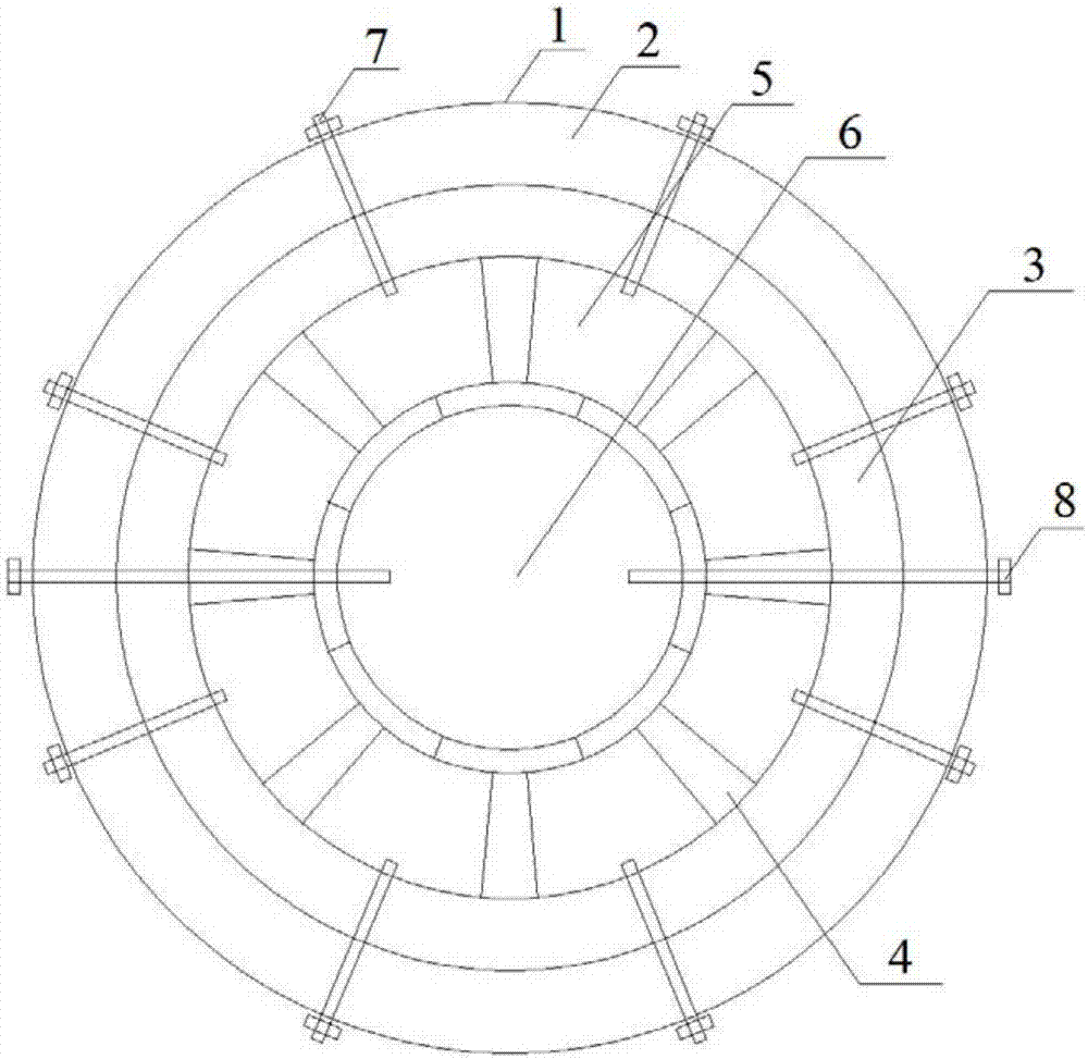
[0033] refer to figure 1 and figure 2 , the activated carbon activation furnace of the present embodiment comprises a body of furnace, a material furnace inlet device 13 and a discharge mechanism 15, the material furnace inlet device 13 is communicated with the feed port of the furnace body, and the discharge mechanism 15 is communicated with the discharge port of the furnace body The furnace body is provided with a combustion passage 6 communicating with the interior of the furnace body. Air is passed through the combustion passage 6. The interior of the furnace body is in a negative pressure state and the air pressure in the combustion passage 6 is lower than that of the furnace body.

[0034] With the current level of technology and methods, the areas in the furnace body cannot be completely relatively sealed, so the combustible gas precipitated by the heating of the material is easy to directly burn in the area where the material is placed, resulting in a large increase i...

Embodiment 2

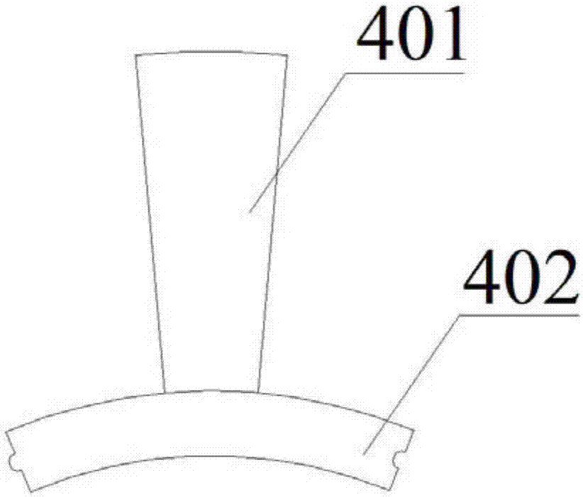
[0049] refer to image 3 , the activated carbon activation furnace of the present embodiment, its structure is basically the same as that of embodiment 1, further:

[0050] In this embodiment, each compartment support 4 includes a compartment support column 401 and a compartment support plate 402, one end of the compartment support column 401 is connected to the inner wall of the outer cylinder 1, and the other end of the compartment support column 401 is connected to the compartment support plate 402. The warehouse supporting plate 402 is connected, and the sub-bin supporting plate 402 is an arc-shaped plate. The sub-bin supporting plate 402 arranged along the circumferential direction encloses a combustion channel 6 with a circular radial cross-section at the center position inside the furnace body. A part of a material channel 5 is enclosed between two adjacent sub-compartment support columns 401, the inner wall of the outer cylinder 1 and the outer wall of the combustion c...

Embodiment 3

[0056] refer to Figure 4 , the active carbon activation furnace of the present embodiment, its structure is basically the same as embodiment 2, further:

[0057] In this embodiment, a material retaining ring 19 is connected to the tail end of the combustion channel 6 , and the inner wall of the material retaining ring 19 is fixed on the outer wall of the combustion channel 6 . During the rotation of the outer cylinder 1, the material channel 5 located at the upper end of the combustion channel 6, because the material is accumulated at the bottom, when the gas in the material channel 5 is sucked into the combustion channel 6, the material particles therein are easily Brought into the combustion channel 6, through the installation of the retaining ring 19, the material accumulated in the material channel 5 which is rotated to the upper part of the combustion channel 6 tail end can be blocked, preventing it from directly falling and being blown into the combustion channel 6.


PUM


Abstract

A furnace body for an activated-carbon activation furnace, which relates to the field of activated-carbon production devices. A burning passage (6) communicating with the inside of the furnace body is disposed in the furnace body. Air is introduced in the burning passage (6). At least two material passages (5) are formed in division of the furnace body, the material passages (5) are disposed along the length direction of the furnace body, and steam is introduced in each material passage (5). The furnace body comprises an outer cylinder (1). At least two sections of branch bin supporting members (4) are disposed along of the circumferential direction of the inner wall of the outer cylinder (1) to form the burning passage (6) in a surrounding manner. Adjacent two sections of branch bin supporting members (4), the inner wall of the outer cylinder (1) and the outer wall of the burning passage (6) define one material passage (5) in a surrounding manner. The safety of an activated-carbon production process can be improved to a certain extent, the furnace body can stably work for a long time, and the quality and the productive capacity of produced activated carbon can be greatly improved.

Description

technical field [0001] The invention relates to the field of activated carbon production equipment, in particular to a furnace body of an activated carbon activation furnace. Background technique [0002] At present, the production methods of activated carbon at home and abroad are mainly divided into two categories, namely: physical method and chemical method. The physical method is to first put the raw materials (high-quality coal, fruit shells, charcoal, etc.) in a closed furnace body for smoldering and carbonization, and then pass in an appropriate amount of water vapor to activate to obtain activated carbon. The chemical method is to impregnate raw materials (usually sawdust) with chemicals (phosphoric acid, zinc chloride, etc.), and then carbonize and activate them in an air-circulating furnace to obtain activated carbon. At present, many manufacturers use physical methods to produce activated carbon. [0003] At present, the equipment for producing activated carbon ...

Claims


Application Information

Patent Timeline
Patent Type & Authority Patents(China)
IPC IPC(8): C01B32/39C01B32/336F27B7/00
CPCF27B7/00
Inventor 张西进
Owner 张西进
Learn More