A spherical plate processing tooling

A spherical and tooling technology, applied in the direction of manufacturing tools, coatings, furnace types, etc., can solve problems such as inability to guarantee machining accuracy and good machining line shape, affecting production construction and progress, and inability to guarantee spherical shape, so as to avoid pitting corrosion. Exceed the standard, save production cost, improve the effect of anti-corrosion effect

Active Publication Date: 2018-03-09
JIANGSU DAJIN HEAVY IND
View PDF11 Cites 0 Cited by
  • Summary
  • Abstract
  • Description
  • Claims
  • Application Information

AI Technical Summary

Problems solved by technology

[0002] At present, the spherical plate cannot be processed directly, and it is usually processed after cutting. However, this method can neither guarantee good processing accuracy and good processing line shape, but also adds a lot of difficulties to the subsequent assembly and welding construction. Serious Affected the construction and schedule of production
Moreover, this method of processing requires a very high technical level of the operator, and the processing time is long and the labor intensity is high.
The processing technology is difficult, the spherical shape cannot be guaranteed, and the productivity is low. For parts with strict spherical shape requirements, the precision requirements cannot be met

Method used


Image

  • A spherical plate processing tooling

Examples


Embodiment 1

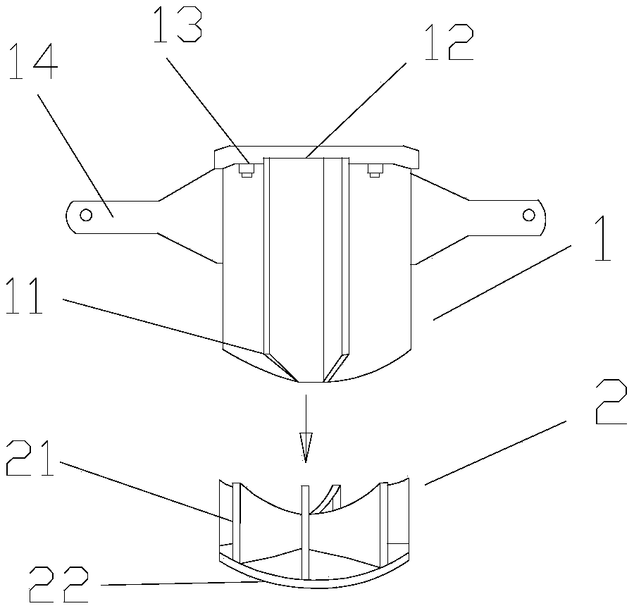
[0019] This embodiment provides a spherical plate processing tool, the structure is as figure 1 As shown, it includes an upper mold 1 and a lower mold 2. The upper mold 1 is welded by a top plate 12 and an upper columnar structure formed by welding one side of six upper ribs 11, and the lower mold 2 includes six lower ribs 21 One side of the plate is welded and connected to form a lower columnar structure and a seat plate 22 arranged at the bottom of the lower columnar structure. The top of the lower columnar structure is provided with a processed recessed end surface, and the curve of the processed recessed end surface is consistent with the curvature of the spherical plate to be processed; the upper mold includes Six upper ribs 11 are welded on one side to form an upper columnar structure and a top plate arranged on the top of the upper columnar structure. The lower end of the upper columnar structure is provided with a processed convex end surface, and the processed convex en...

Embodiment 2

[0029] The structure of this embodiment is the same as that of embodiment 1, and the difference is that the upper and lower ribs of this embodiment adopt the composition of high-strength alloy tool steel and the difference in surface coating. The high-strength alloy tool steel of this embodiment In terms of mass percentage, it includes the following specific components:

[0030] C: 0.95%, Ni: 12%, Cr: 0.91%, Mn: 5.3%, Si: 0.19%, Als: 0.024%, Mo: 0.37%, Nb: 0.18%, Cu: 0.91%, N: 0.09%, S: 0.032%, P: 0.05%, Ti: 0.18%, V: 0.03%, B: 0.003%, lanthanide rare earth: 1.3%, the balance is Fe;

[0031] The mass percentages of lanthanide rare earth components are: cerium: 25%, praseodymium: 14%, holmium: 19%, erbium: 15%, the balance is lanthanum, and the sum of the above components is 100%;

[0032] The manufacturing process of this high-strength alloy tool steel is as follows:

[0033] ⑴ Continuous casting billet heating: the continuous casting billet heating temperature is 1180℃, and the heat...

Embodiment 3

[0038] The structure of this embodiment is the same as that of embodiment 1, and the difference is that the upper and lower ribs of this embodiment adopt the composition of high-strength alloy tool steel and the difference in surface coating. The high-strength alloy tool steel of this embodiment In terms of mass percentage, it includes the following specific components:

[0039] C: 1.05%, Ni: 13%, Cr: 1.10%, Mn: 6.0%, Si: 0.23%, Als: 0.030%, Mo: 0.43%, Nb: 0.20%, Cu: 0.95%, N: 0.11%, S: 0.035%, P: 0.05%, Ti: 0.24%, V: 0.03%, B: 0.004%, lanthanide rare earth: 1.4%, the balance is Fe;

[0040] The mass percentages of the lanthanide rare earth components are: cerium: 27%, praseodymium: 17%, holmium: 22%, erbium: 16%, the balance is lanthanum, and the sum of the above components is 100%;

[0041] The manufacturing process of this high-strength alloy tool steel is as follows:

[0042] ⑴ Continuous casting billet heating: the continuous casting billet heating temperature is 1200℃, and the ...


PUM


Abstract

The invention discloses a machining tool for a spherical plate. The tool comprises an upper mold and a lower mold, wherein the lower mold comprises a lower columnar structure defined through welding connection of sides of at least three lower rib plates and a seat plate arranged at the bottom of the lower columnar structure; a machining concave end surface is arranged at the top of the lower columnar structure, and the curve of the machining concave end surface is consistent with the radian of a curved surface of the to-be-machined spherical plate; the upper mold comprises an upper columnar structure defined through welding connection of sides of at least three upper rib plates and a top plate arranged at the top of the upper columnar structure; and a machining convex end surface is arranged at the lower end of the upper columnar structure and is matched with the machining concave end surface in radian. The smooth degree of the appearance of the plate can be guaranteed with the tool, assembly, electric welding and polishing in following processes can be reduced, the manufacturing period of the spherical plate can be shortened, and the manufacturing cost of the spherical plate can be saved.

Description

Technical field [0001] The invention relates to a processing device, in particular to a processing tool for a three-dimensional curved spherical plate, and belongs to the technical field of special-shaped plate processing. Background technique [0002] At present, spherical plates cannot be processed directly. They are usually processed after cutting. However, this method can not guarantee good processing accuracy and good processing line, and it also adds many difficulties to the subsequent assembly and welding construction. Affected the construction and schedule of production. Moreover, this method of processing requires extremely high technical level of the operator, long processing time and high labor intensity. The processing technology is difficult, the spherical shape cannot be guaranteed, and the productivity is low. For parts with strict requirements on the spherical shape, the accuracy requirements cannot be met. Summary of the invention [0003] The technical problem ...

Claims


Application Information

Patent Timeline
Patent Type & Authority Patents(China)
IPC IPC(8): C22C38/08C22C38/04C22C38/32C22C38/02C22C38/06C22C38/12C22C38/16C22C38/14C22C33/04C21D9/00C09D4/02C09D4/06C09D5/08C09D7/61C09D7/63
CPCC09D4/06C09D5/08C21D9/00C22C33/04C22C38/005C22C38/02C22C38/04C22C38/06C22C38/08C22C38/12C22C38/14C22C38/16C22C38/32
Inventor 石亚飞吴有军陈恒金
Owner JIANGSU DAJIN HEAVY IND
Why Eureka
Try Eureka