Engine brake method for vehicle retardance

A technology of engine braking and engine, which is applied in the direction of engine control, machine/engine, mechanical equipment, etc., can solve the problems of fuel nozzle tip burnout, insufficient, high engine temperature, etc., to eliminate high load and high exhaust temperature, improve The effect of reliability and durability

Inactive Publication Date: 2017-01-04
SHANGHAI UNIVERSOON AUTOPARTS CO LTD
View PDF7 Cites 17 Cited by
  • Summary
  • Abstract
  • Description
  • Claims
  • Application Information

AI Technical Summary

Problems solved by technology

[0012] The object of the present invention is to provide an engine braking method for slowing down the vehicle. The method will solve the technical problem of the engine braking in the prior art that the braking power is too low at medium and low speeds, especially to solve the current There are technical problems that the engine temperature is too low when the engine brakes at medium and low speeds, the fuel cannot be ignited or the combustion is insufficient, and there are technical problems that the engine temperature is too high when the engine brakes at high speeds, and the tip of the fuel nozzle burns out

Method used


Image

  • Engine brake method for vehicle retardance
  • Engine brake method for vehicle retardance
  • Engine brake method for vehicle retardance

Examples


Embodiment 1

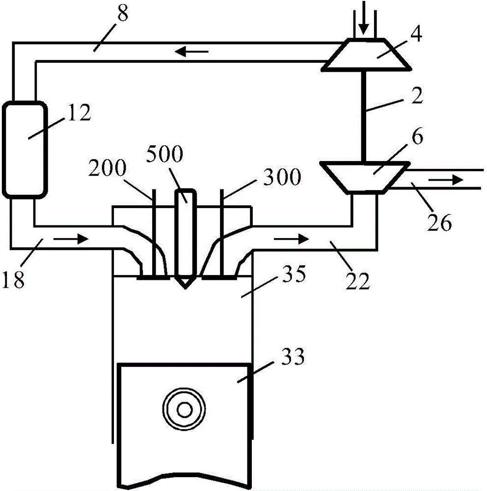
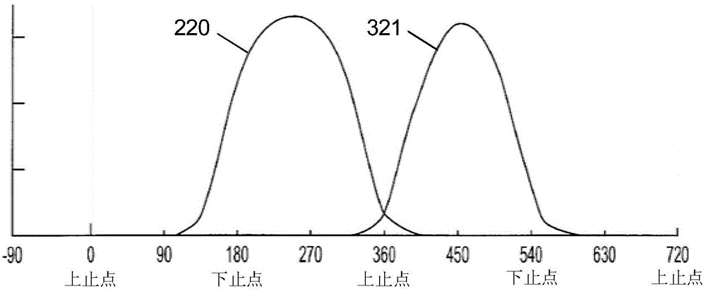
[0081] figure 1 and figure 2 Used to describe the ignition operation of a conventional four-stroke engine. General engines have multiple cylinders. For example, the engine on a commercial vehicle is an inline six-cylinder diesel engine. But for brevity, figure 1 and figure 2 Only one engine cylinder and the movement of that cylinder's valve in one cycle are shown. The piston 33 of the engine performs periodic motions up and down in the cylinder 35 . As mentioned above, each cycle of motion of a four-stroke engine includes an intake stroke, a compression stroke, an expansion (or working) stroke, and an exhaust stroke. During the intake stroke, figure 1 The engine piston 33 in the cylinder 35 starts from the exhaust top dead center ( figure 2 360° in the middle) to the intake bottom dead center ( figure 2 540°) movement in the engine, the intake valve 200 of the engine opens, resulting in figure 2 The intake valve profile 321 in the intake valve introduces air into...

Embodiment 2

[0089] The difference between the second embodiment of the engine braking method of the present invention and the first embodiment is that not only fuel is injected into the engine cylinder in this embodiment, but also other gaseous or liquid media, such as air and water. wait. Although the injected air and water cannot be burned, it is possible to increase the pressure in the cylinder and the resistance of the piston to the top dead center, thereby increasing the braking power of the engine. If the temperature in the cylinder is high enough, the sprayed water may turn into steam and increase the pressure in the cylinder.

[0090] The working process of this embodiment is similar to that of the first embodiment, and will not be repeated here.

Embodiment 3

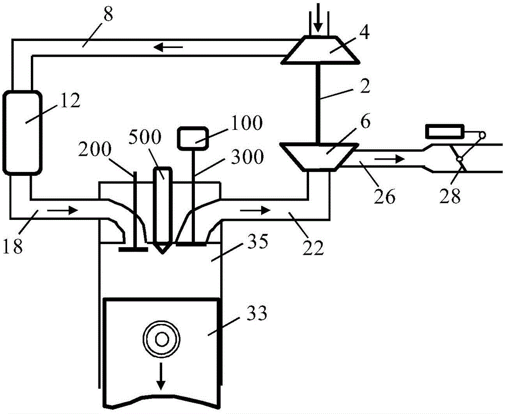
[0092] The difference between this embodiment and the above-mentioned first or second embodiment is that this embodiment does not directly inject medium into the cylinder of the engine, but injects air into the exhaust pipe of the engine, and then adjusts the exhaust pressure of the engine and opens the exhaust pipe. The door, which forces the air injected into the exhaust pipe into the cylinders of the engine.

[0093] The operation process of the engine braking method of this embodiment can be through Figure 6 to illustrate. Compared with the first embodiment, this embodiment adds an air injection mechanism, including an air compressor 41 (the diesel engine of a general commercial vehicle is equipped with an air compressor), an air injection pipeline 43 and an air injection valve 45 . The air injection pipeline 43 communicates with an outlet of the air compressor and the exhaust pipe 22 of the engine, and the air injection valve 45 is arranged on the outlet of the air comp...


PUM


Abstract

An engine brake method for vehicle retardance is provided. An engine operates at preset rotating speed (especially medium and low rotating speed); exhausting pressure of the engine can be adjusted via an exhausting current-limiting device (such as a turbocharger and an exhausting butterfly valve), so temperature of the engine can be controlled and medium of a preset volume can be ejected into an air cylinder or an exhausting pipe of the engine to increase cylinder internal pressure and motion resistance of a piston of the engine, thereby increasing engine braking power. When fuel oil working as medium is ejected into the cylinder, combustion of the fuel oil is controlled during compression stroke of the engine, so cylinder internal pressure and engine braking power can be further improved. A problem of low braking power of the engine at medium and low rotating speed in the prior art can be solved, and engine brake at high rotating speed can be reduced and even avoided; failure modes such as high load and high exhausting temperature due to high rotating speed brake can be eliminated; and reliability and durableness of engine brake operation can be improved.

Description

[0001] Technical field: [0002] The invention relates to the field of machinery, in particular to the field of engines, in particular to an engine braking method for vehicle deceleration. [0003] Background technique: [0004] Vehicle engines have a long history of use in the prior art, and conventional firing of engines is well known. For example, a four-stroke diesel engine operates repeatedly in cycles, with an intake stroke, compression stroke, expansion (or working) stroke, and exhaust stroke within each cycle. During the intake stroke, the piston of the engine moves from top dead center to bottom dead center in the cylinder, and the intake valve of the engine opens to introduce air into the cylinder of the engine. Next is the compression stroke, the piston moves from the bottom dead center to the top dead center, the intake valve and exhaust valve of the engine are closed, the air in the cylinder is compressed, and when the piston reaches the top dead center, diesel is...

Claims


Application Information

Patent Timeline
Patent Type & Authority Applications(China)
IPC IPC(8): F02D13/04
Inventor 奚勇杨洲
Owner SHANGHAI UNIVERSOON AUTOPARTS CO LTD
Why Eureka
Try Eureka