Magnetic field shielding cover of cusped magnetic field thruster

A tangent magnetic field and thruster technology, applied in the field of electric thrusters, can solve the problems of satellite electronic equipment interference, excessive induction strength, etc., and achieve the effect of improving the working temperature environment

Inactive Publication Date: 2017-01-04
HARBIN INST OF TECH
View PDF6 Cites 9 Cited by
  • Summary
  • Abstract
  • Description
  • Claims
  • Application Information

AI Technical Summary

Problems solved by technology

[0004] The purpose of the present invention is to solve the problem that the peripheral magnetic induction intensity of the cusped magnetic field thruster is too strong, causing serious interference to satellite electronic equipment, and provides a magnetic field shield for the cusped magnetic field thruster

Method used


Image

  • Magnetic field shielding cover of cusped magnetic field thruster
  • Magnetic field shielding cover of cusped magnetic field thruster
  • Magnetic field shielding cover of cusped magnetic field thruster

Examples


specific Embodiment approach 1

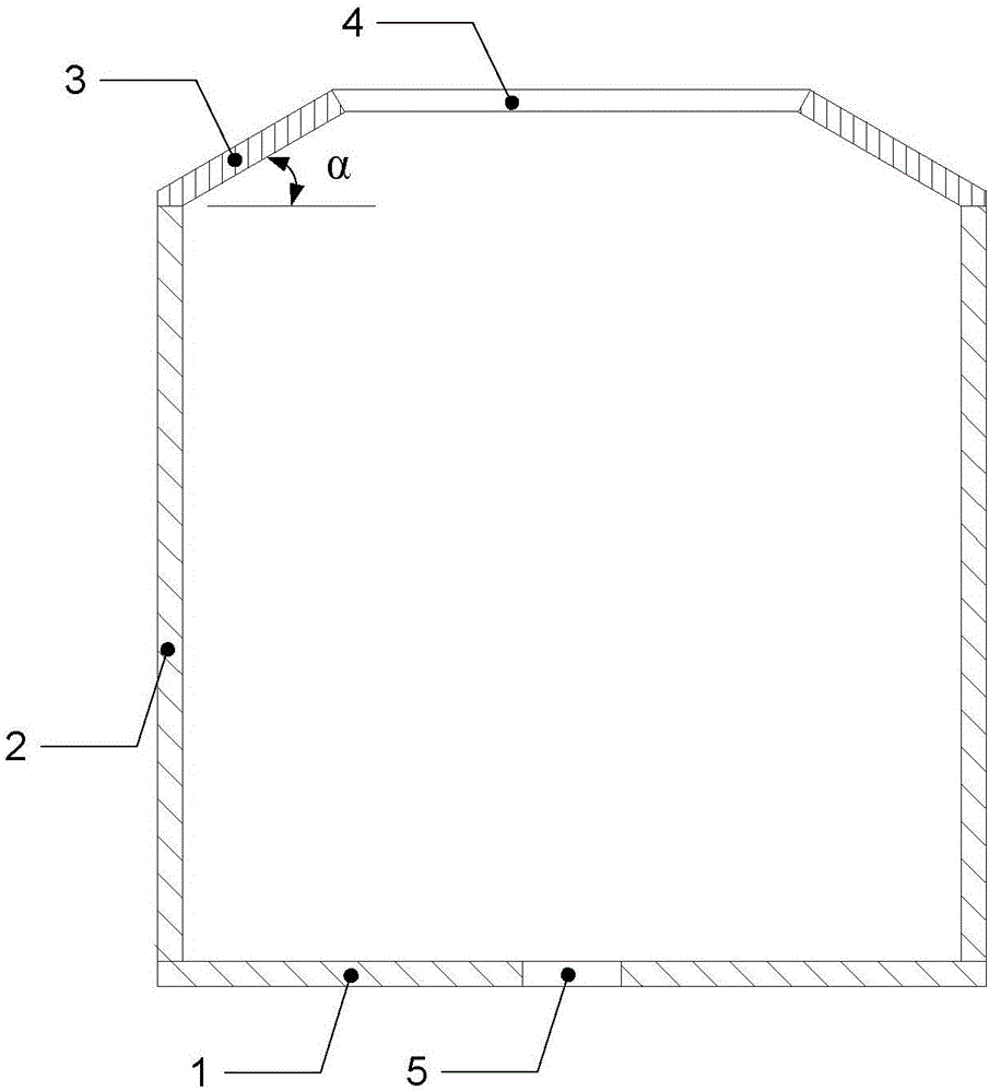
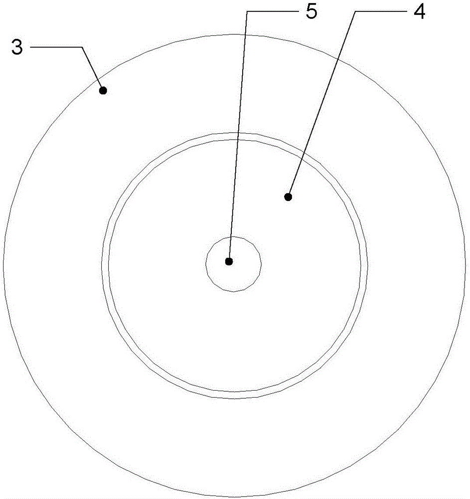
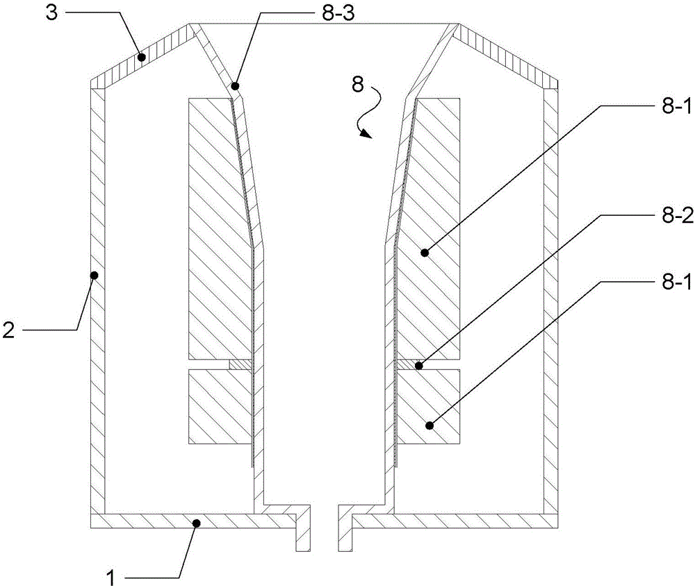
[0026] Specific implementation mode one: the following combination Figure 1 to Figure 7 Describe this embodiment, the magnetic field shield of the cusp magnetic field thruster described in this embodiment is as follows figure 1 As shown, there is no fixing device in this embodiment, the bottom plate 1 and the cylinder body 2 are integrally processed into an upwardly open drum structure, the upper opening is welded with a cover 3, the cover 3 is a frustum-shaped cylindrical structure, the large port of the cover 3 is connected with the cylinder The upper port of the body 2 is welded together, and the small port of the cover 3 is used as the ceramic outlet mounting hole 4. Installed on the cusp magnetic field thruster 8, the shielding cover is used as its shell, the outlet of the ceramic discharge channel 8-3 is fixed with the ceramic outlet mounting hole 4, and the entrance of the ceramic discharge channel 8-3 is at the 5 places of the ceramic inlet mounting hole, which will b...

specific Embodiment approach 2

[0029] Specific implementation mode two: the following combination Figure 8 to Figure 15 This embodiment will be described. This embodiment will further describe the first embodiment. Four fixed feet 6 are installed on the same horizontal plane as the outer circle of the bottom plate 1, and the thruster is fixed at a fixed position outside through the positioning installation hole 7.

[0030] The magnetic field distribution after installing the fixed foot 6 is as follows Figure 11 As shown, compared with the distribution of magnetic induction intensity without fixed feet, the external magnetic field distribution of the thruster is seriously affected, and the magnetic induction intensity of the corresponding external parts has been significantly enhanced.

[0031] Moreover, in this embodiment, the four fixed legs 6 are evenly distributed along the circumference, so as to reduce the influence of the fixed legs 6 on the overall shielding effect.

[0032] A specific example is ...


PUM


Abstract

The invention discloses a magnetic field shielding cover of a cusped magnetic field thruster, and belongs to the field of electric thrusters. The problem that the cusped magnetic field thruster is too high in periphery magnetic induction intensity to cause serious disturbance to satellite electronic equipment is solved. The magnetic field shielding cover comprises a bottom plate, a cylinder body and a cover body. The cylinder body is of a cylinder structure with the uniform diameter. The bottom plate arranged at a lower port of the cylinder body and the cylinder body are integrally machined and formed. The center position of the bottom plate is provided with a ceramic inlet installation hole. An upper port of the cylinder body is provided with the cover body. The cover body is of a cylinder structure in a circular truncated cone shape. A large port of the cover body and the upper port of the cylinder body are welded together, and a small port of the cover body is used as a ceramic outlet installation hole. The included angle alpha between the circular truncated cone generatrix of the cover body and the bottom face of the cover body is larger than the largest plume angle of the thruster, and the circular truncated cone generatrix of the cover body is perpendicular to the circular truncated cone generatrix of the outlet section of a discharge ceramic channel.

Description

technical field [0001] The invention belongs to the field of electric propulsion. Background technique [0002] The tangential magnetic field thruster is an electric thruster that utilizes the principle of a traveling wave tube. By arranging several magnets with the same magnetic poles opposite to each other to form a magnetic field cross section, that is, to form a magnetic mirror, the electrons emitted from the cathode are constrained by this special magnetic circuit. Under the acceleration of the electric field, the electrons will obtain high energy. The final result is that the electromagnetic field confines the electrons and makes the electrons gain energy, and collides with the neutral gas xenon in the discharge channel to ionize it to obtain plasma, which is ejected under the acceleration of the electric field to generate thrust. This process involves electromagnetic fields, and this type of electric propulsion system needs to reach a maximum magnetic field of about ...

Claims


Application Information

Patent Timeline
Patent Type & Authority Applications(China)
IPC IPC(8): F03H1/00H05K9/00
CPCF03H1/0087H05K9/0071
Inventor 刘辉蒋文嘉毛威扈延林于达仁
Owner HARBIN INST OF TECH
Why Eureka
Try Eureka