
Pressure compensation device and method for detecting whether compensated device leaks oil

A pressure compensation and compensation device technology, applied in transmission parts, by measuring the acceleration and deceleration rate of fluid, using liquid/vacuum for liquid tightness measurement, etc. Complicated and other problems, to achieve the effect of easy operation, simple structure, convenient and quick pressure compensation

Inactive Publication Date: 2017-01-04
周德吉
View PDF6 Cites 7 Cited by
  • Summary
  • Abstract
  • Description
  • Claims
  • Application Information

AI Technical Summary

Problems solved by technology

However, in harsh environments, such as acidic or alkaline mud mixed with various stones, such bladders, diaphragms or pistons are easily cut or corroded when they are in direct contact with the mud outside.
[0004] An active control pressure compensation technology is also mentioned in the prior art, which actively sets the internal pressure of the transmission to make the internal pressure of the transmission higher than, equal to or lower than the external pressure, especially when the compensation pressure is higher than the external pressure. At this time, the gear oil in the transmission device can only leak to the outside, and no foreign substances will leak into the transmission device. Although this technology can better protect the transmission device, the existing structure is too complicated, and the pressure data Acquisition components and active control actuators have high requirements

Method used


Image

  • Pressure compensation device and method for detecting whether compensated device leaks oil
  • Pressure compensation device and method for detecting whether compensated device leaks oil
  • Pressure compensation device and method for detecting whether compensated device leaks oil

Examples


Embodiment 1

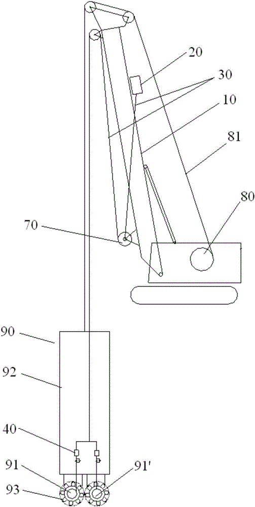
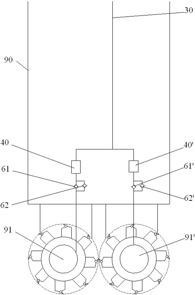
[0046] This specific embodiment discloses a pressure compensating device, which is connected with a transmission device working in water or mud, and is used for pressure compensation of the transmission device. Such as figure 1 and figure 2 As shown, the pressure compensating device in this embodiment is connected with a slot milling machine 90 for foundation construction. The slot milling machine 90 includes a transmission device 91, 91', a frame 92 and a milling wheel 93. The whole slot milling machine 90 is hoisted 80 and steel wire rope 81 will sink into the mud environment for operation, therefore, it is necessary to carry out pressure compensation to the transmission device 91 of the milling machine 90.

[0047] Such as figure 1 and figure 2 As shown, the pressure compensating device disclosed in this specific embodiment includes: a bracket 10; a liquid storage tank 20, fixed on the bracket 10, located above the working liquid level where the transmission device 91 ...

Embodiment 2

[0058] Since the density of the gear oil is lower than that of the mud, as the depth increases, the pressurized value generated by the height difference between the liquid storage tank and the construction liquid level will gradually decrease, and finally it will be less than the external pressure. Therefore, Embodiment 1 It is only applicable to the situation that the construction depth of the groove milling machine 90 is relatively shallow.

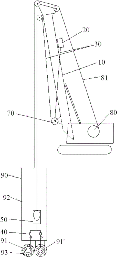
[0059] The pressure compensation device disclosed in the second embodiment is basically the same as the first embodiment, the difference is that the pressure compensation device in the second embodiment also includes a two-liquid separation box 50, by setting the two-liquid separation box 50, the pressure compensation can be made The device is applicable to the situation that the construction depth of the groove milling machine 90 is relatively deep.

[0060] Such as image 3 and Figure 4 As shown, the two-liquid separation box 50 in...

Embodiment 3

[0068]The invention also discloses a method for detecting whether the compensated device is leaking oil, the compensated device is a transmission device connected to the pressure compensating device, comprising the steps of:

[0069] S10: the liquid storage tank delivers liquid to the transmission device through the pipeline;

[0070] S20: monitor the flow of the liquid in the pipeline through a flowmeter;

[0071] S30: judging whether the flow rate monitored by the flowmeter exceeds the preset flow rate;

[0072] S40: If yes, the compensated device leaks oil, and sends out a first alarm message; if not, the compensated device does not leak oil or the oil leak is not serious;

[0073] S50: Monitoring the internal and external pressure difference of the compensated device through the pressure sensor;

[0074] S60: judging whether the pressure difference monitored by the pressure sensor exceeds a first preset pressure difference (usually 2-4 ar);

[0075] S70: If yes, send ou...


PUM


Abstract

The invention discloses a pressure compensation device and a method for detecting whether a compensated device leaks oil. The pressure compensation device is connected with a transmission device working in water or slurry and is used for carrying out pressure compensation on the transmission device. The pressure compensation device comprises a support, a liquid storage tank, a pipeline and flow meters. The liquid storage tank is fixed to the support and located over the working liquid level of the transmission device. The starting end of the pipeline is communicated with the liquid storage tank, and the tail end of the pipeline is communicated with the transmission device. The flow meters are arranged on the pipeline and used for monitoring the flow of liquid in the pipeline, and whether the monitored flow is larger than a preset flow value is judged so as to judge whether the transmission device leaks oil. The pressure compensation device is simple in structure and high in safety and reliability, and no movable component is exposed in slurry; in the method for detecting whether the compensated device leaks oil, few steps are needed, operation is easy, whether the compensated device leaks oil can be accurately and rapidly judged, and then corresponding remedial measures can be taken in time.

Description

technical field [0001] The invention relates to the structural design of underwater construction devices and the technical field of oil leakage detection, in particular to a pressure compensation device and a method for detecting oil leakage of a compensated device. Background technique [0002] For transmissions working in an environment with increased pressure (such as in water or mud), the internal and external pressure difference of the transmission will cause seal damage. In order to reduce the risk of seal damage, it is necessary to perform pressure compensation inside the transmission to ensure The internal pressure of the transmission is balanced with the external pressure or the internal pressure is slightly higher than the external pressure. [0003] Most of the current pressure compensation devices sink into the water together with the transmission device when working, relying on the deformation or movement of the flexible bladder, diaphragm or piston device of th...

Claims


Application Information

Patent Timeline
Patent Type & Authority Applications(China)
IPC IPC(8): F16H57/00E02F5/08E02F5/14G01M3/26
CPCF16H57/00E02F5/08E02F5/14E02F5/145G01M3/26
Inventor 周德吉
Owner 周德吉
Learn More