
Pressure sintering furnace with rapid cooling function

A pressure sintering and rapid cooling technology, which is applied in the field of pressure sintering furnaces, can solve the problems of simple cooling methods, slow convective heat exchange, and low cooling efficiency, and achieve the effects of ensuring cycle efficiency, improving production efficiency, and improving cooling effect

Active Publication Date: 2017-01-04
ZIGONG CHANGCHENG EQUIP TECH
View PDF4 Cites 12 Cited by
  • Summary
  • Abstract
  • Description
  • Claims
  • Application Information

AI Technical Summary

Problems solved by technology

The existing cooling method of the furnace body is too simple, only by opening the furnace door and allowing the hot and cold gases inside and outside the furnace to naturally and slowly convect heat to achieve cooling, the cooling efficiency is low, so it is necessary to design a pressure sintering furnace with cooling function to Realize the rapid cooling of products and improve production efficiency

Method used


Image

  • Pressure sintering furnace with rapid cooling function
  • Pressure sintering furnace with rapid cooling function
  • Pressure sintering furnace with rapid cooling function

Examples


Embodiment Construction

[0024] The present invention will be further described below in conjunction with the accompanying drawings and specific embodiments.

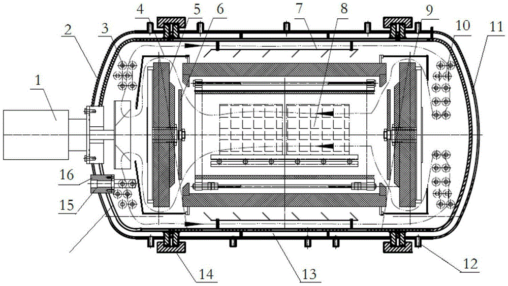
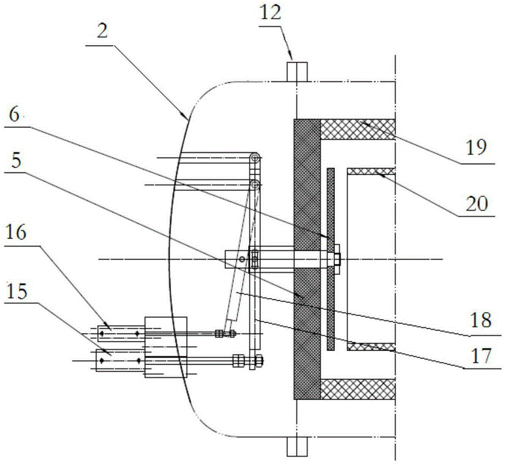
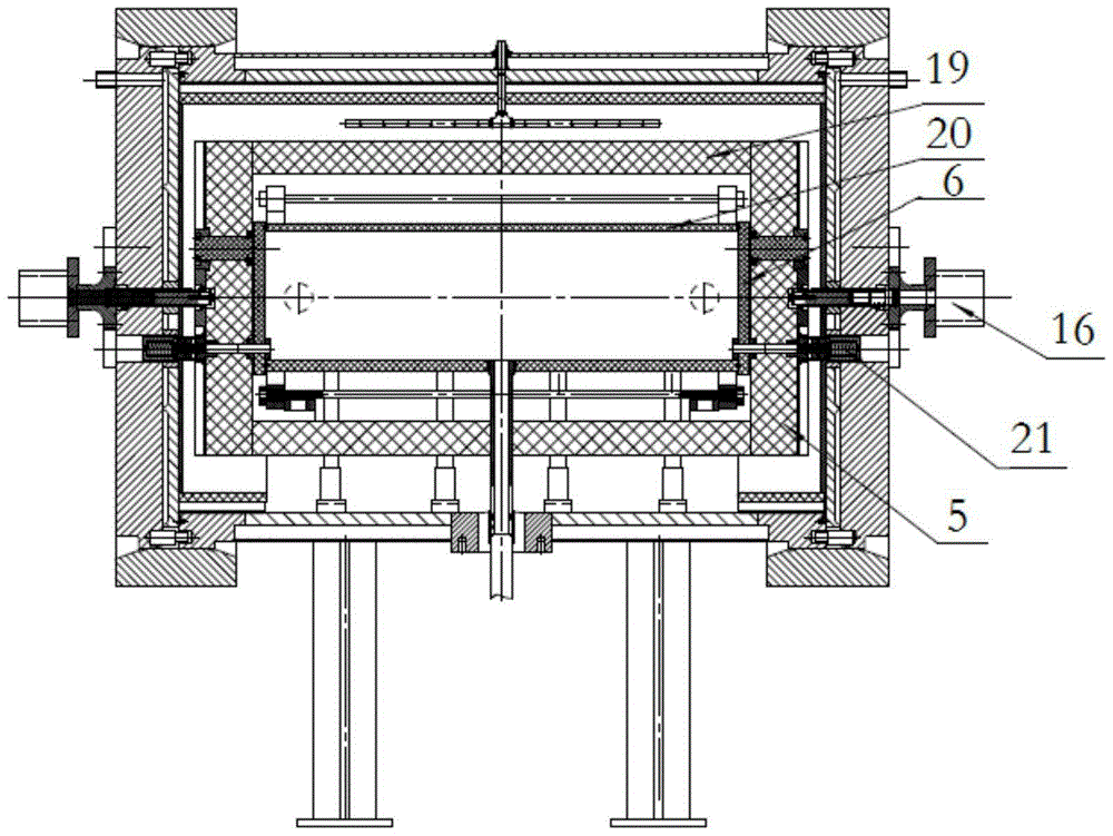
[0025] Such as figure 1 , figure 2 As shown, the present invention comprises blower fan 1, furnace door, furnace body, heat exchanger, gas deflector cover, airflow deflector 7, cooling water inlet and outlet pipe 12, furnace shell water jacket 13, heat preservation door cylinder 15 and material box The door cylinder 16 and the insulation door 5, material box door 6, insulation tube 19 and high-temperature product area 8 arranged in the furnace body; the high-temperature product area 8 is supported by a graphite base plate and a graphite support column installed in the furnace body. A material box 20 is arranged in the high-temperature product area 8 .

[0026]Fan 1 is a high-power water-cooled fan with a water-cooling jacket and cooling water inlet and outlet pipes. The fan 1 is provided with blades. The furnace door is a front furnace do...


PUM

PropertyMeasurementUnit
diameteraaaaaaaaaa

Abstract

The invention provides a pressure sintering furnace with a rapid cooling function. The pressure sintering furnace with the rapid cooling function comprises a draught fan, heat exchangers, gas diversion covers, airflow diversion plates, cooling water inlet and outlet pipes, a furnace shell water jacket, thermal insulation door air cylinders, material box door air cylinders, furnace doors and a furnace body. Thermal insulation doors, material box doors, thermal insulation cylinders and a high temperature product area are arranged in the furnace body; and material boxes are arranged in the high temperature product area. The draught fan and the heat exchangers are installed on the furnace doors; the heat exchangers are connected with the cooling water inlet and outlet pipes correspondingly; the gas diversion covers are installed on the corresponding thermal insulation doors and attached to the corresponding thermal insulation cylinders; the airflow diversion plates are uniformly distributed on the periphery of the inner wall of a furnace shell; the cooling water inlet and outlet pipes communicate with the furnace shell water jacket, and the furnace shell water jacket is located between the furnace shell and the inner wall of the furnace body; carbon felt doors and the material box doors are of a double-air-cylinder independent opening-closing structure; and the thermal insulation door air cylinders and the material box door air cylinders are installed on the corresponding furnace doors and connected with the thermal insulation doors and the material box doors correspondingly. The pressure sintering furnace with the rapid cooling function is stable and reliable in using, improves production efficiency and product quality, and is especially suitable for sintering of small-sized hard alloy products.

Description

technical field [0001] The invention relates to a cemented carbide pressure sintering furnace, in particular to a pressure sintering furnace with rapid cooling function. Background technique [0002] At present, the sintering of cemented carbide generally adopts pressure sintering furnace, which eliminates the microscopic pores of the alloy through sintering hot isostatic pressing, improves the hardness, density and bending strength of the product, and improves the quality of the alloy product. 6MPa pressure sintering furnace and 1.6Mpa pressure furnace are mainly used for cemented carbide products of different grades and sizes of sintering furnaces, for large-sized products (such as cemented carbide roll rings) and low-cobalt grade products (Co content below 8%) Mainly use 6Mpa pressure furnace for sintering. For small-sized products (such as cemented carbide blades) and high-cobalt grade products (Co content above 8%), 1.6Mpa pressure furnace is mainly used for sintering....

Claims


Application Information

Patent Timeline
Patent Type & Authority Applications(China)
IPC IPC(8): F27B21/00F27B21/08F27D1/18F27D9/00
Inventor 范昆
Owner ZIGONG CHANGCHENG EQUIP TECH
Learn More