Optical structure tool for stray light resisting test of star sensor and testing method

A technology of optical structure and star sensor, applied in the field of astronautical starry sky detection, can solve the problems of high experiment cost, limited operation period by time and space, limited storage energy, etc., and achieve the effect of improving reliability.

Active Publication Date: 2017-01-04
SHANGHAI AEROSPACE CONTROL TECH INST
View PDF5 Cites 17 Cited by
  • Summary
  • Abstract
  • Description
  • Claims
  • Application Information

AI Technical Summary

Problems solved by technology

However, the operation period of this test method is limited by time and space, and the experimental cost is relatively high: each test requires a solar simulator with a suitable caliber, and the test location is a clear field night without stray light pollution
Due to the limited energy stored in the built-in power supply of the solar simulator, it cannot be tested in the field environment for a long time
According to the reasons listed above, it is not suitable to test its anti-stray light ability in the field in the early stage of star sensor development

Method used


Image

  • Optical structure tool for stray light resisting test of star sensor and testing method
  • Optical structure tool for stray light resisting test of star sensor and testing method
  • Optical structure tool for stray light resisting test of star sensor and testing method

Examples


Embodiment Construction

[0040] The present invention will be described in further detail below in conjunction with the accompanying drawings and embodiments.

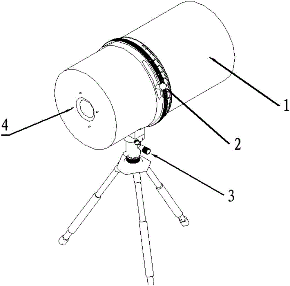
[0041] The present invention provides an optical structure tooling with controllable sunlight spot (hereinafter referred to as optical structure tooling), which is applied to the anti-stray light test of the star sensor in the optical darkroom laboratory. By changing the output spot diameter of the solar simulator, The background ambient light interference is reduced during the stray light test, and the test accuracy of the star sensor in the darkroom environment is improved.

[0042] Such as figure 1 As shown, the optical structure tooling is provided with a light blocking barrel 1, a digital variable aperture 2, three stray light elimination apertures, solar cells, a high-precision optical mirror, a portable adjustable tripod 3, Extinction cone.

[0043] Wherein, the direction of the large aperture of the light blocking barrel 1 is aligned...


PUM


Abstract

The invention provides an optical structure tool for a stray light resisting test of a star sensor and a testing method. A light blocking barrel equipped with a planar coating with high absorptivity and extinction cones inside is arranged, a digital display variable diaphragm and stray light eliminating diaphragms are mounted in the light blocking barrel, and a light transmitting aperture is formed in the light output direction of the tool, or a solar battery cell and a high-precision optical reflector are mounted in the light output direction of the tool. The area of an output light spot is controlled by adjusting the diameter of the digital display variable diaphragm in the light blocking barrel, light spots outside a light hood of the star sensor can be prevented from irradiating test background space, meanwhile, the stray light caused by the diffraction phenomenon is reduced by means of the stray light eliminating diaphragms, so that the light interference of the background environment is reduced in the stray light testing process, and the testing precision of the star sensor in a darkroom environment is improved.

Description

technical field [0001] The invention relates to an aerospace-type starry sky detection technology, in particular to an optical structure tooling and a test method applied to the anti-stray light test of a star sensor. Background technique [0002] The anti-stray light test of star sensor is an indispensable test link in the development process of star sensor. The best way to test the star sensor's resistance to stray light is to use a solar simulator whose output spot just covers the entire star sensor hood in a cloudless environment at night. However, the operation cycle of this test method is limited by time and space, and the cost of the experiment is relatively high: each test requires a solar simulator with a suitable caliber, and the test location is a clear field night without stray light pollution. Due to the limited energy stored in the built-in power supply of the solar simulator, it cannot be tested in the field environment for a long time. According to the reas...

Claims


Application Information

Patent Timeline
Patent Type & Authority Applications(China)
IPC IPC(8): G01C25/00
CPCG01C25/00
Inventor 杜伟峰孙少勇杨宵史晓王燕清
Owner SHANGHAI AEROSPACE CONTROL TECH INST
Why Eureka
Try Eureka