
Current boosting device, current transformer and current testing method

A technology of current transformer and current boosting, which is applied in the direction of measuring current/voltage, measuring device, and only measuring current, etc. It can solve problems such as large transformation ratio of current transformer, overvoltage, and small current of secondary winding W2

Inactive Publication Date: 2017-01-04
STATE GRID CORP OF CHINA +1
View PDF4 Cites 1 Cited by
  • Summary
  • Abstract
  • Description
  • Claims
  • Application Information

AI Technical Summary

Problems solved by technology

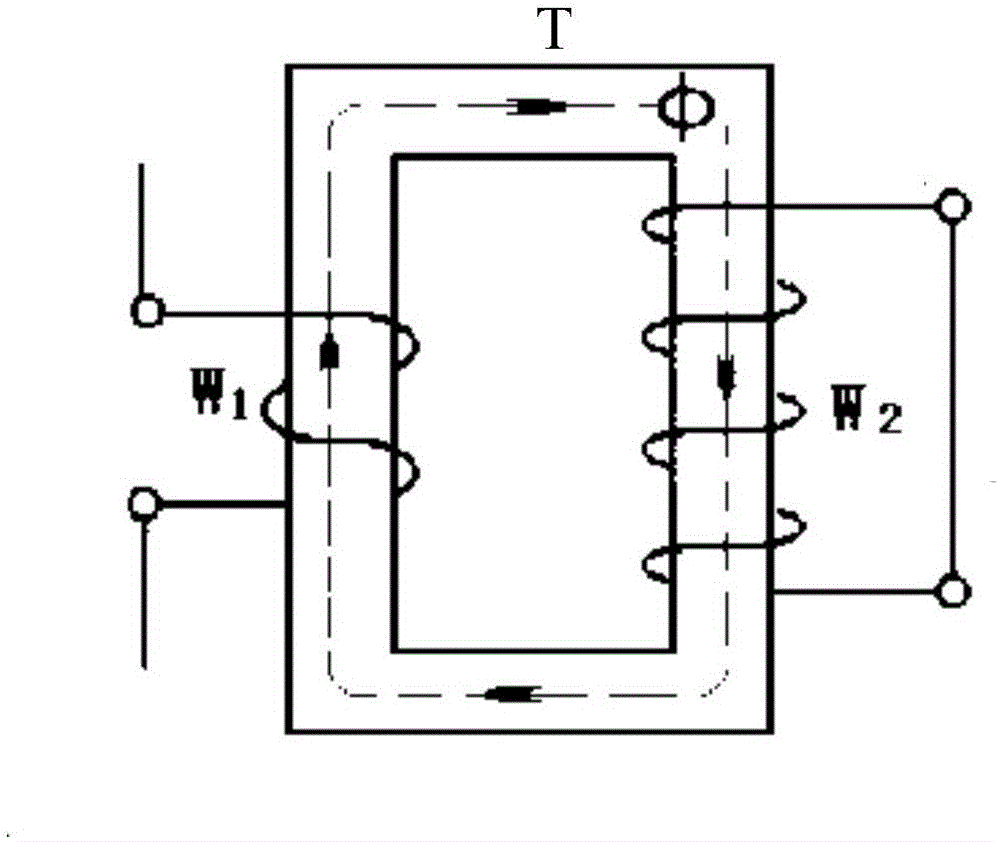
[0003] The number of turns of the primary winding W1 is much less than the number of turns of the secondary winding W2, which makes the transformation ratio of the general current transformer very large (usually above 2500 / 1); and because in the power system, Due to problems such as line length, transmission capacity, and inherent parameters of the line, overvoltages are generated at the receiving end of the line. Therefore, in EHV / UHV, reactors are often connected in parallel at the end of the line in the substation at the receiving end. However, this method will make The capacitive current of the line to the ground and the parallel reactance cancel each other, so that the current at one end of the secondary winding W2 of the current transformer is too small, so that the amplitude and phase of the current to be measured cannot be measured; in addition, for short-distance lines and large substations The low-voltage system also has the problem that the current at one end of the secondary winding W2 of the current transformer is too small

Method used


Image

  • Current boosting device, current transformer and current testing method
  • Current boosting device, current transformer and current testing method
  • Current boosting device, current transformer and current testing method

Examples


Embodiment Construction

[0034] The following will clearly and completely describe the technical solutions in the embodiments of the present invention with reference to the accompanying drawings in the embodiments of the present invention. Obviously, the described embodiments are only some, not all, embodiments of the present invention. Based on the embodiments of the present invention, all other embodiments obtained by persons of ordinary skill in the art without making creative efforts belong to the protection scope of the present invention.

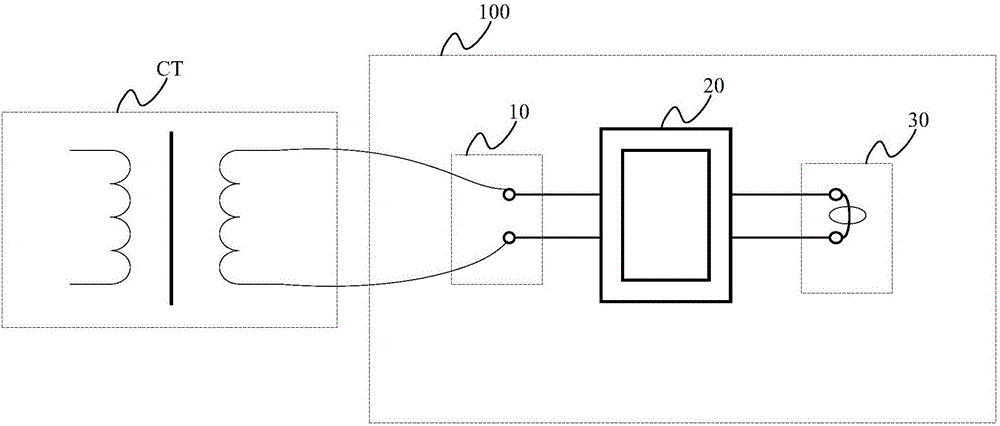
[0035] An embodiment of the present application provides a current boosting device, which is applied to a current transformer, and the secondary winding of the current transformer is open, such as figure 2 shown, including:

[0036] A connection part 10 for connecting with the secondary winding of the current transformer CT;

[0037] It is connected to one end of the wiring part 10 away from the current transformer CT and wound on the input coil on the side ...


PUM


Abstract

The invention discloses a current boosting device, a current transformer and a current testing method, wherein the current boosting device is applied in the current transformer and a secondary open winding of the current transformer. The current boosting device comprises the components of a wiring part which is used for connecting with the secondary winding of the current transformer; an input coil which is connected with one end of the wiring part and winds one side of a magnetic core, wherein the side of the wiring part deviates from the current transformer; an output coil which winds the other side of the magnetic core; wherein the magnetic core is made of silicon steel sheet; and a measuring part which is connected with the output coil in an end-to-end manner, wherein a turn ratio between the input coil and the output coil is a preset number which is larger than 1. The current boosting device prevents incapability of measuring amplitude and phase of the to-be-measured current caused by oversmall current at the secondary winding side of the current transformer. Furthermore because the magnetic core is made of the silicon steel sheet with relatively high resistivity and highest magnetic conductivity, loss current reduction of the magnetic core is realized, thereby reducing loss of the magnetic core, and furthermore improving current amplifying capability of the current boosting device.

Description

technical field [0001] The present application relates to the technical field of current phase measurement, and more specifically, to a current boosting device, a current transformer and a current testing method. Background technique [0002] In the power system, the current transformer is an important component to ensure accurate measurement and correct action of the protection. It is also the main connection component of the primary and secondary automation protection in the substation system, which has a direct impact on the safe operation of the power system. Its main structure is as figure 1 As shown, it includes a closed iron core T, a primary winding W1 wound on one side of the closed iron core T, and a secondary winding W2 wound on the other side of the closed iron core T; the primary winding W1 is used for series connection In the circuit of the current to be measured, the secondary winding W2 is a closed winding, which is used to convert the current to be measured...

Claims


Application Information

Patent Timeline
IPC IPC(8): G01R19/00G01R15/18
CPCG01R15/183G01R19/0092
Inventor 李振动宋巍王翀王艳召张金祥陈军法柏峰赵伟刘启蒙汤煜东李奕炜周生海孙松强高峥牛雪飞任文雪史然然于文博冯学敏杨洁
Owner STATE GRID CORP OF CHINA
Learn More