Organic light-emitting display panel

A technology of light-emitting display and organic light-emitting elements, which is applied in instruments, semiconductor devices, computing, etc., and can solve the problem of failure of touch function, high requirements for the production of protective film layer, polarizer and cover plate, and the inability to realize touch-sensitive flexible display Panel thinning and other issues to achieve the effect of avoiding breakage

Active Publication Date: 2017-01-04
SHANGHAI TIANMA MICRO ELECTRONICS CO LTD +1
View PDF4 Cites 27 Cited by
  • Summary
  • Abstract
  • Description
  • Claims
  • Application Information

AI Technical Summary

Problems solved by technology

[0004] 1. Attaching the touch module to the flexible display panel, this method often cannot realize the thinning of the touch-sensitive flexible display panel
[0005] 2. Integrate the touch electrodes on the protective film layer, polarizer or cover plate. Although this method can reduce the thickness of the touch-sensitive flexible display panel to a certain extent, it is harmful to the thickness of the protective film layer, polarizer plate and cover plate. Production requirements are higher
[0006] Moreover, when the above-mentioned touch-sensitive flexible display panel is bent, cracks are likely to occur on the surface, and the cracks are easy to extend and expand, so that the touch-control electrodes are likely to break, resulting in failure of the touch-control function.
In addition, the touch traces connected to the touch electrodes are easily corroded by the influence of oxygen and water vapor in the environment, which affects the effect of touch control and display

Method used


Image

  • Organic light-emitting display panel
  • Organic light-emitting display panel
  • Organic light-emitting display panel

Examples


Embodiment Construction

[0025] The present invention will be further described in detail below with reference to the drawings and embodiments. It can be understood that the specific embodiments described here are only used to explain the present invention, but not to limit the present invention. In addition, it should be noted that, for ease of description, the drawings only show a part but not all of the structure related to the present invention.

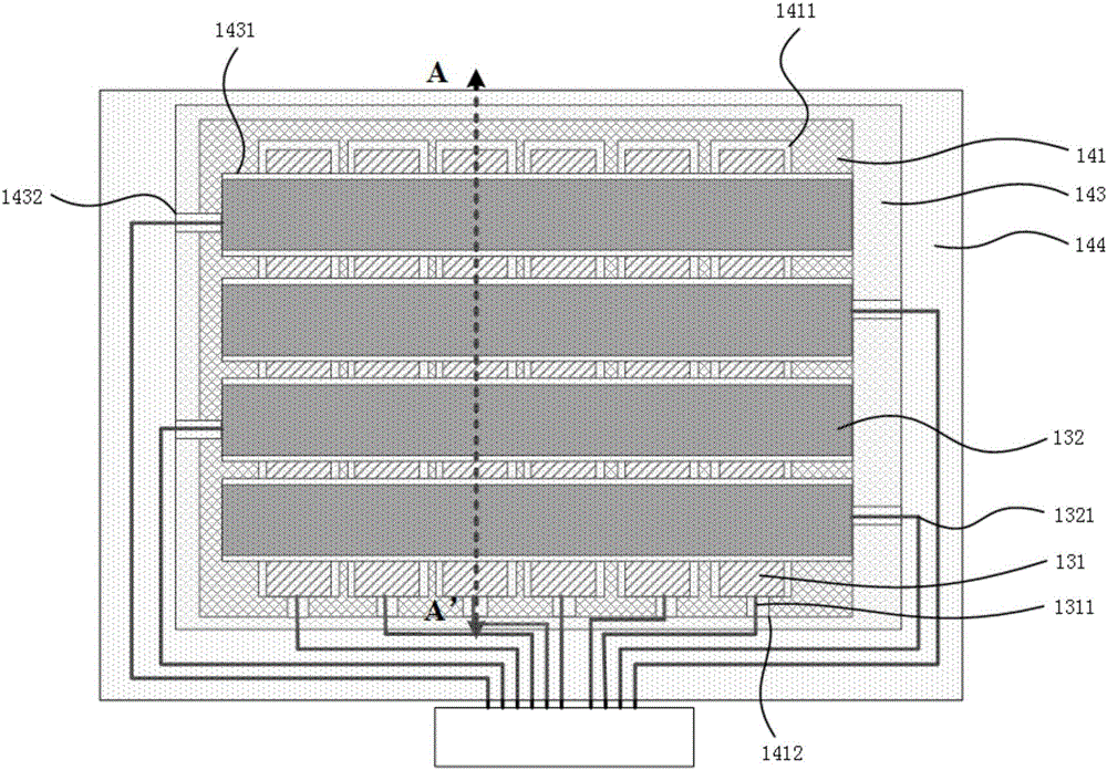
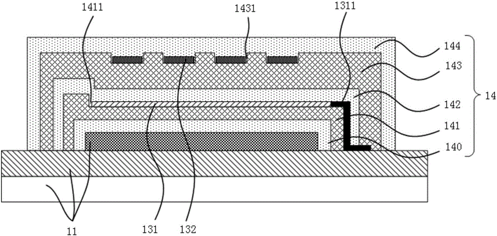
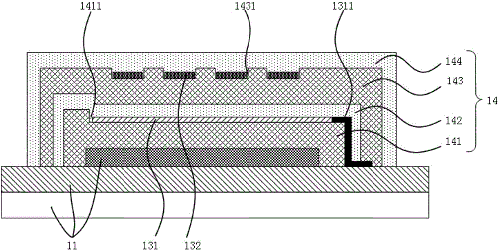
[0026] Figure 1a It is a schematic top view of an organic light emitting display panel provided by an embodiment of the present invention. Figure 1b For the edge Figure 1a Schematic diagram of the cross-sectional structure in the AA' direction. Combine Figure 1a with Figure 1b As shown, the organic light-emitting display panel provided by this embodiment includes an organic light-emitting element array substrate 11, a thin-film encapsulation layer 14 covering the organic light-emitting element array substrate 11, a plurality of touch drive electrodes 131,...


PUM


Abstract

The invention discloses an organic light-emitting display panel. The organic light-emitting display panel comprises an organic light-emitting element array substrate, a thin-film encapsulation layer covering the organic light-emitting element array substrate, a plurality of touch-control driving electrodes, a plurality of touch-control sensing electrodes, a plurality of first touch-control routing lines, and a plurality of second touch-control routing lines, wherein the first touch-control routing lines are electrically connected with the corresponding touch-control driving electrodes; the second touch-control routing lines are electrically connected with the corresponding touch-control sensing electrodes; the thin-film encapsulation layer comprises a first organic layer and a second organic layer; a plurality of first grooves and a plurality of second grooves are formed in the first organic layer, and a plurality of third grooves and a plurality of fourth grooves are formed in the second organic layer; the touch-control driving electrodes are located in the first grooves, and the first touch-control routing lines are located in the second grooves; the touch-control sensing electrodes are located in the third grooves, and the second touch-control routing lines are located in the fourth grooves; the first touch-control routing lines and the second touch-control routing lines are located in the thin-film encapsulation layer. The organic light-emitting display panel provided by the invention is used for meeting the requirement that the touch-control routing lines are not easy to corrode.

Description

Technical field [0001] The embodiments of the present invention relate to the field of display technology, and in particular to an organic light emitting display panel. Background technique [0002] With the rapid development of display technology, breakthroughs have been made in both display screen size and display quality. As an important development direction of display technology, flexible display devices are attracting attention for their lightness, thinness and flexibility. The touch-sensitive flexible display panel combines the advantages of touch technology and flexible display technology. It not only has the characteristics of changeable or bendable, but also can be directly operated by the user with a finger or a stylus, which is very comfortable and convenient. s concern. [0003] At present, most of the touch electrodes of touch-sensitive flexible display panels are externally mounted or integrated in an external auxiliary film, which are roughly divided into the foll...

Claims


Application Information

Patent Timeline
Patent Type & Authority Applications(China)
IPC IPC(8): G06F3/041H01L27/32
CPCG06F3/0412H10K59/40
Inventor 刘雪宁柳晨蔡雨
Owner SHANGHAI TIANMA MICRO ELECTRONICS CO LTD
Why Eureka
Try Eureka