Minitype broadband circularly polarized antenna

A circularly polarized antenna and broadband technology, applied in the direction of the connection of the antenna grounding switch structure and the structural form of the radiating element, can solve the problems of reducing the antenna gain, reducing the radiation efficiency, increasing the loss of the dielectric plate, etc., to extend the current path, reduce the Antenna size, the effect of broadening the bandwidth

Active Publication Date: 2017-01-04
NO 20 RES INST OF CHINA ELECTRONICS TECH GRP
View PDF3 Cites 15 Cited by
  • Summary
  • Abstract
  • Description
  • Claims
  • Application Information

AI Technical Summary

Problems solved by technology

Increasing the dielectric constant of the dielectric substrate can reduce the dielectric wavelength of the microstrip antenna and achieve the purpose of reducing the size of the radiation patch, but a higher dielectric constant will increase the loss of the dielectric plate to a certain extent, reduce the ...

Method used


Image

  • Minitype broadband circularly polarized antenna
  • Minitype broadband circularly polarized antenna
  • Minitype broadband circularly polarized antenna

Examples


Embodiment Construction

[0027] The present invention will be further described below in conjunction with the accompanying drawings and embodiments, and the present invention includes but not limited to the following embodiments.

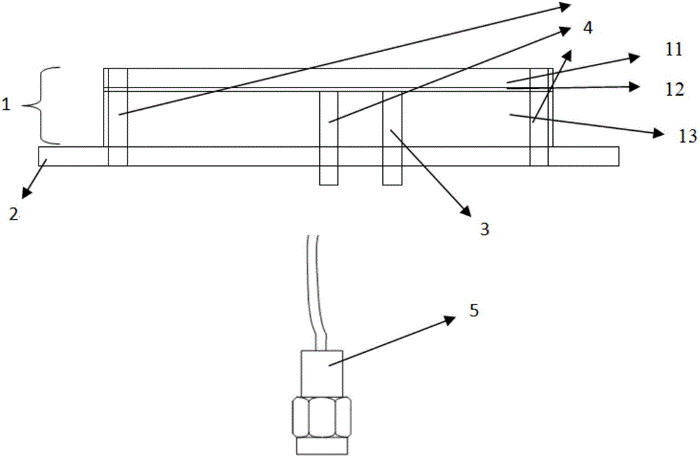
[0028] The invention includes an antenna printed board, a feed board, a feed probe, a short-circuit probe and a radio frequency cable.

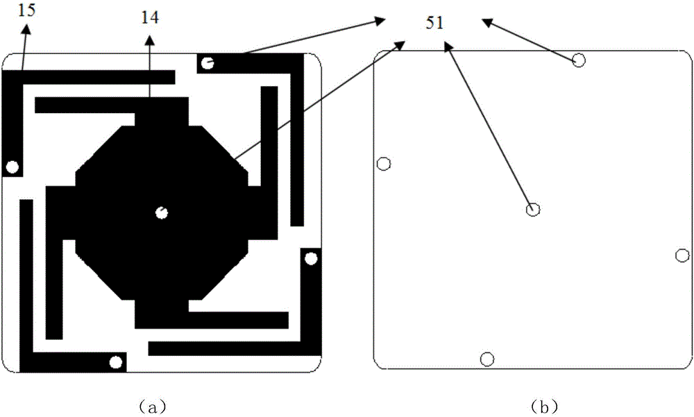
[0029] The antenna printed board includes a coupling radiation dielectric board, an adhesive layer, and a supporting dielectric board. The copper-clad upper layer of the coupling radiation medium board has a dielectric constant of 9.6 and a thickness of 1mm, and the upper layer copper-clad part is the upper layer radiation patch. The upper radiation patch is composed of the main radiation patch in the middle and four L-shaped perturbation element radiation patches on the edge, and the radiation patch in the middle is connected to the metal ground of the lower layer of the supporting medium board and the feeder board through a short-circuit...


PUM

PropertyMeasurementUnit
Diameteraaaaaaaaaa
Thicknessaaaaaaaaaa
Thicknessaaaaaaaaaa

Abstract

The invention provides a minitype broadband circularly polarized antenna. The minitype broadband circularly polarized antenna comprises a coupled radiation dielectric plate, a bonding layer, a support dielectric plate and a feeding panel which are attached in sequence, wherein the feeding panel is located below the support dielectric plate, and is connected with a feeding probe through a grounding probe. The antenna bandwidth is effectively broadened through coupled feeding among the coupled radiation dielectric plate, the support dielectric plate and the feeding panel, the grounding probe load effectively reduces the size of the antenna, and the coupled radiation dielectric plate loads an L-type perturbation element to extend the current path, reduce the size of the antenna and broaden the axis ratio bandwidth of the antenna. On the basis of guaranteeing gain, the minitype broadband circularly polarized antenna effectively reduces the volume of the antenna, increases the bandwidth of the antenna, and meets the requirements of various systems for the size and performance of the antenna.

Description

technical field [0001] The invention relates to a microstrip antenna, which can be applied to wireless communication or to receive satellite navigation signals. Background technique [0002] Since the microstrip antenna can easily obtain circularly polarized radiation characteristics, it has a very wide range of applications in the development of various modern communication systems. With the development of science and technology, the requirements of communication systems for circularly polarized antennas are gradually increasing. The current antennas not only need to achieve circularly polarized axial ratio and impedance characteristics, but also hope that circularly polarized antennas have other characteristics, such as multi-frequency, Broadband high gain, miniaturization, etc. [0003] Usually, the receiving antenna of satellite navigation terminal adopts the basic form of microstrip antenna, which has the advantages of low profile, easy conformal shape, simple structur...

Claims


Application Information

Patent Timeline
IPC IPC(8): H01Q1/38H01Q1/50
CPCH01Q1/38H01Q1/50
Inventor 张佳张海光许奎尤浩梁西铭张骅赵晶郭卫展李明
Owner NO 20 RES INST OF CHINA ELECTRONICS TECH GRP
Why Eureka
Try Eureka