Optical fiber amplifier gain control method and device

A fiber amplifier and gain control technology, applied in the communication field, can solve the problems of low ASE compensation accuracy and slow differential control rate, etc., and achieve the effect of improving ASE compensation accuracy and differential control rate

Active Publication Date: 2017-01-04
NANJING ZHONGXING XIN SOFTWARE CO LTD
View PDF5 Cites 13 Cited by
  • Summary
  • Abstract
  • Description
  • Claims
  • Application Information

AI Technical Summary

Problems solved by technology

[0017] The invention provides a method and device for controlling the gain of an optical fiber amplifier to at least solve the problems of low ASE compensation accuracy and slow differential control speed of the optical fiber amplifier in the related art

Method used


Image

  • Optical fiber amplifier gain control method and device
  • Optical fiber amplifier gain control method and device
  • Optical fiber amplifier gain control method and device

Examples


Embodiment Construction

[0074] Hereinafter, the present invention will be described in detail with reference to the drawings and examples. It should be noted that, in the case of no conflict, the embodiments in the present application and the features in the embodiments can be combined with each other.

[0075] It should be noted that the terms "first" and "second" in the description and claims of the present invention and the above drawings are used to distinguish similar objects, but not necessarily used to describe a specific sequence or sequence.

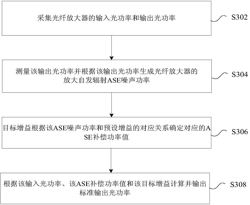
[0076] In this embodiment, a fiber amplifier gain control method is provided, image 3 It is a flow chart of a method for controlling the gain of an optical fiber amplifier according to an embodiment of the present invention, such as image 3 As shown, the process includes the following steps:

[0077] Step S302, collecting the input optical power and output optical power of the optical fiber amplifier;

[0078] Step S304, measuring the output optic...


PUM


Abstract

The invention provides an optical fiber amplifier gain control method and device. According to the invention, the method comprises the steps: employing a digital device to replace an original closed-loop simulation control unit, and calculating the final output optical power in a current control mode according to the gain and output optical power set values through combining with ASE compensation power; The method carries out the smoothing of the inputted optical power, and achieves an effect of discrete noise elimination. Meanwhile, the method carries out the compensation of the inputted signal to some extent. The method improves the dynamic performance of a system through employing a differential control algorithm and an integral control algorithm, and the period when the whole closed-loop control system completes one-time control is about 1 us. The method can effectively achieve the gain and power locking, meets the requirements of dynamic and steady indexes of a user, solves problems that the ASE compensation precision of an optical fiber amplifier is not high and the differential control rate is slow, and improves the ASE compensation precision of the optical fiber amplifier and the differential control rate.

Description

technical field [0001] The invention relates to the field of communication, in particular to a method and device for controlling the gain of an optical fiber amplifier. Background technique [0002] Erbium Doped Fiber Amplifier (EDFA for short) is a key component of a new generation of optical communication systems. The rate has nothing to do with the data format, and it is an essential key component in a large-capacity wavelength division multiplexing (Dense Wavelength Division Multiplexing, referred to as DWDM) system. The effective working range of EDFA is for the C-band of the DWDM system, the center frequency is 193.1THz, the wavelength range is 1528-1561nm, and the channel spacing is an integer multiple of 100GHz (about 0.8nm), including 40 waves in total. [0003] Because the DWDM system is a multi-wavelength working system, and because the erbium-doped fiber amplifier EDFA has saturation characteristics, the wavelength power in the saturation region remains stable. ...

Claims


Application Information

Patent Timeline
Patent Type & Authority Applications(China)
IPC IPC(8): H01S3/10H01S3/067
CPCH01S3/06754H01S3/1608H01S2301/02H01S2301/06H04B10/073
Inventor 朱墨
Owner NANJING ZHONGXING XIN SOFTWARE CO LTD
Why Eureka
Try Eureka