
Wireless power transfer system and power transfer method thereof

A wireless power transmission and wire technology, applied in electrical components, circuit devices, etc., can solve the problems of reduced transmission efficiency and low transmission efficiency, and achieve the effect of saving occupied space, realizing amplification, and improving transmission efficiency.

Inactive Publication Date: 2017-01-04
BEIJING POLYTECHNIC COLLEGE +1
View PDF5 Cites 11 Cited by
  • Summary
  • Abstract
  • Description
  • Claims
  • Application Information

AI Technical Summary

Problems solved by technology

[0004] However, in the prior art, when the size of the receiving coil is much smaller than the size of the transmitting coil, the transmission efficiency of the wireless power transmission system is much smaller than that of a completely symmetrical wireless power transmission system with the same size of the transmitting coil and the receiving coil
In the actual wireless power transmission system, long-distance and small-sized receiving coils often appear. For example, when charging wireless mobile devices such as mobile phones, the size of the receiving coil in the mobile phone is much smaller than the size of the transmitting coil. In this wireless power transmission system , the transmission efficiency will be greatly reduced

Method used


Image

  • Wireless power transfer system and power transfer method thereof
  • Wireless power transfer system and power transfer method thereof
  • Wireless power transfer system and power transfer method thereof

Examples


Embodiment Construction

[0027] In order to make the purpose, technical solutions and advantages of the embodiments of the present invention clearer, the technical solutions in the embodiments of the present invention will be clearly and completely described below in conjunction with the drawings in the embodiments of the present invention. Obviously, the described embodiments It is a part of embodiments of the present invention, but not all embodiments.

[0028] Based on the embodiments of the present invention, all other embodiments obtained by persons of ordinary skill in the art without making creative efforts belong to the protection scope of the present invention. In the case of no conflict, the following embodiments and features in the embodiments can be combined with each other.

[0029] It should be noted that, in the description of the present invention, the terms "first" and "second" are only used to describe different components conveniently, and should not be understood as indicating or i...


PUM


Abstract

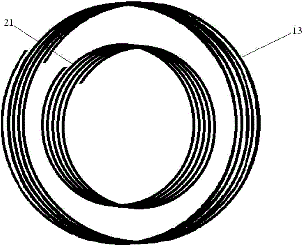
The invention discloses a wireless power transfer system and a power transfer method thereof, and relates to the magnetically-coupled resonant wireless power transfer technology. The wireless power transfer system comprises a high-frequency signal generator, a power amplifier, a transmitting coil and a receiving coil, wherein the power amplifier is connected between the transmitting coil and the high-frequency signal generator; a repeating coil is arranged on the inner side of the transmitting coil; the repeating coil is coupled to the transmitting coil; the repeating coil and the transmitting coil are coaxial and coplanar; the receiving coil is coupled to the repeating coil; the receiving coil is further connected with loading equipment; the transmitting coil, the repeating coil and the receiving coil are made of magnetically-plated conductors. Through arrangement of the repeating coil coaxial and coplanar with the transmitting coil, a mutual inductance coefficient between the transmitting coil and the repeating coil is greatly increased, amplification of source current is achieved, and the power transfer efficiency is improved. In addition, through coaxial and coplanar arrangement of the repeating coil and the transmitting coil, the space occupation of the wireless power transfer system can be also reduced.

Description

technical field [0001] The invention relates to magnetic coupling resonance wireless power transmission technology, in particular to a wireless power transmission system and a power transmission method thereof. Background technique [0002] As early as the middle and late 19th century, the famous electrical engineer Nikola Tesla proposed the concept of Wireless Power Transfer (WPT) technology, and carried out related experimental research using the principle of wireless power transfer, which laid a foundation for the future wireless power transfer technology. The development of transmission technology has laid a theoretical and practical foundation. Since then, wireless power transmission technology has received more and more attention and research. With the rise of research on wireless power transfer technology, more and more applications have entered our lives, such as maglev trains, electric vehicles, tailless appliances, and biomedicine. [0003] At present, the wirele...

Claims


Application Information

Patent Timeline
Patent Type & Authority Applications(China)
IPC IPC(8): H02J50/12H02J50/50
CPCH02J5/005
Inventor 任凤国翟志颖张中华赵伟郭凯程伟王文清
Owner BEIJING POLYTECHNIC COLLEGE
Learn More