Unlock instant, AI-driven research and patent intelligence for your innovation.

voltage converter

A voltage converter and switching voltage technology, which is applied in the direction of output power conversion devices, instruments, electrical components, etc., can solve the problems of output signal VOUT voltage value drop, unable to reflect the state current of load state changes, etc., to achieve the goal of improving performance Effect

Active Publication Date: 2018-12-21
EXCELLIANCE MOS
View PDF3 Cites 0 Cited by
  • Summary
  • Abstract
  • Description
  • Claims
  • Application Information

AI Technical Summary

Problems solved by technology

[0004] Depend on figure 2 It can be clearly seen that in the existing voltage converter 100, the DC component of the ramp signal RAMP will increase due to the increase of the current on the inductor L1 caused by the decrease of the load current ILOAD, while the voltage of the feedback signal VFB then decreases as the load current ILOAD decreases
Therefore, the signal provided by the ripple injection circuit 120 to the amplifiers OP1 and OP2 (the ramp signal RAMP plus the feedback signal VFB) cannot reflect the changing state current of the load state. Therefore, the comparison voltage COMP cannot respond to a large change in the load state. to adjust, resulting in a significant drop in the voltage value of the output signal VOUT

Method used


Image

  • voltage converter
  • voltage converter
  • voltage converter

Examples


Embodiment Construction

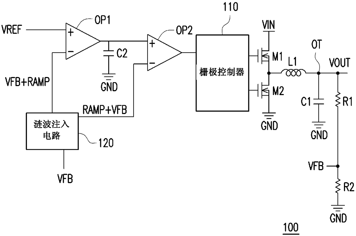
[0062] Please refer to below image 3 , image 3 A schematic diagram of a voltage converter according to an embodiment of the invention is shown. The voltage converter 300 includes a fixed on-time signal generator 310, transistors M1, M2, an inductor L1, a ripple signal compensator 330, and a ripple injection circuit 320. The output signal VOUT is generated on the output terminal OT of the voltage converter 300, where the voltage converter 300 may be a step-down voltage converter. The output signal VOUT can generate the feedback signal VFB through the voltage divider circuit formed by the resistors R1 and R2. The fixed on-time signal generator 310 provides a driving signal to the control terminals (eg, gates) of the transistors M1 and M2, and is used to control the on or off state of the transistors M1 and M2. The transistors M1 and M2 are serially connected between the power supply voltage VIN and the reference ground terminal GND in sequence. The first terminal of the trans...


PUM


Abstract

The invention provides a voltage converter, which includes a constant conduction time signal generator, a first transistor, a second transistor, an inductor, a ripple signal compensator and a ripple injection circuit. The ripple signal compensator is coupled to the output terminal of the voltage converter and the second terminal of the first transistor, and generates an adjusted ripple signal according to the switching voltage of the second terminal of the first transistor and the output signal of the voltage converter. The ripple injection circuit generates a ripple injection signal according to the adjusted ripple signal. Wherein, the constant on-time signal generator generates the first and second driving signals according to the ripple injection signal and the reference voltage to respectively drive the first transistor and the second transistor. Therefore, the voltage converter of the present invention can respond quickly when the load state is switched, and effectively provide a stable output signal.

Description

Technical field [0001] The invention relates to a voltage converter, in particular to a step-down voltage converter capable of quickly stabilizing the output signal provided by the voltage converter. Background technique [0002] Please refer to figure 1 , figure 1 A circuit diagram of a prior art voltage converter is shown. The existing voltage converter 100 includes a gate controller 110, a ripple injection circuit 120, amplifiers OP1, OP2, transistors M1, M2, capacitors C1, C2, resistors R1, R2, and inductor L1. The gate controller 110 periodically provides a driving signal to control the on or off state of the transistors M1 and M2, and thereby generates an output signal VOUT. [0003] Please refer to the following synchronously figure 1 as well as figure 2 ,among them figure 2 The dynamic waveform diagram of the gate controller 110 when the load state changes is shown. When the load state of the voltage converter 100 changes (for example, from a light load to a heavy load)...

Claims


Application Information

Patent Timeline
Patent Type & Authority Patents(China)
IPC IPC(8): H02M3/158
CPCH02M3/156H02M1/0025H02M3/1566
Inventor 谢孟儒林宝全
Owner EXCELLIANCE MOS