Video camera on basis of flight time technologies

A time-of-flight, camera technology, applied in image communication, color TV components, TV system components, etc., can solve the problems that cameras cannot accurately detect and track moving targets, cannot compare and judge, etc., to enhance friendliness and convenience, solving the effect of inability to accurately detect and track

Inactive Publication Date: 2017-01-04
江苏云光智慧信息科技有限公司
View PDF0 Cites 1 Cited by
  • Summary
  • Abstract
  • Description
  • Claims
  • Application Information

AI Technical Summary

Problems solved by technology

[0004] 1. The camera can only obtain the two-dimensional information of the target on the projection plane of the camera and the size of the target on the projection plane. The detected target information is actually the two-dimensional information of the target on the projection plane of the camera, not the target itself in three-dimensional space , so that it is impossible to compare and judge with the actual spatial position information
[0005] 2. When the moving targets overlap, the camera cannot accurately detect and track the moving targets
[0006] 3. When the moving target is still, the camera cannot accurately detect and track the moving target

Method used


Image

  • Video camera on basis of flight time technologies
  • Video camera on basis of flight time technologies

Examples


Embodiment Construction

[0021] The present invention will be described in detail below in conjunction with the accompanying drawings and embodiments.

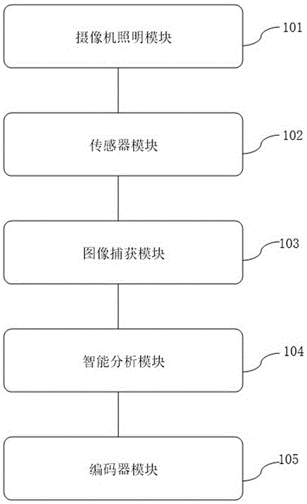
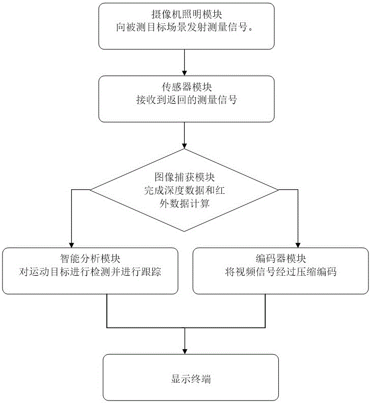
[0022] figure 1 It is a schematic diagram of the internal structure of a camera based on the time-of-flight technology of the present invention; figure 2 It is a schematic flow chart of a camera based on the time-of-flight technology of the present invention when it is working.

[0023] Such as Figure 1 to Figure 2 As shown, a camera based on time-of-flight technology of the present invention includes: a camera lighting module 101, a sensor module 102, an image capture module 103, an intelligent video analysis module 104, and a video encoder module 105, and these modules are connected in sequence.

[0024] The camera lighting module 101 is used for transmitting measurement signals to the measured target scene.

[0025] The sensor module 102 includes an image sensor, a photodiode array, an electron beam control circuit, and a reading circuit, and ...


PUM


Abstract

The invention discloses a video camera on the basis of flight time technologies. The video camera comprises a video camera illumination module, a sensor module, an image capturing module, an intelligent video analyzing module and a video encoder module which are sequentially connected with one another. The video camera has the advantages that brightness information and distance information of moving targets can be efficiently caught in real time, and three-dimensional information of the moving targets can be sufficiently presented; the video camera is free of influence of external light environments or detected target and background environment contrast, the moving targets can be accurately tracked, the problem of incapability of accurately detecting and tracking existing moving targets when the existing moving targets are overlapped or are still can be effectively solved, and the user and system interaction friendliness and convenience can be improved.

Description

technical field [0001] The invention relates to the field of security monitoring, in particular to a camera based on time-of-flight technology. Background technique [0002] Night vision monitoring in the prior art all adopts infrared camera technology at present. Infrared camera is divided into passive infrared camera and active infrared camera. Passive infrared photography uses the principle that any object emits infrared light above absolute zero (-273°C). Passive infrared does not emit infrared rays, but relies on the infrared radiation of the target itself to form a thermal image, so it is also called a thermal imager. The principle of active infrared camera is to use a light projection device to emit infrared light to the monitoring area, and the infrared light reflected back from the monitoring area is received by the camera device, after photoelectric conversion and circuit amplification comparison, corresponding signals are generated, and then transmitted to the c...

Claims


Application Information

Patent Timeline
Patent Type & Authority Applications(China)
IPC IPC(8): H04N5/225H04N5/232
CPCH04N23/50H04N23/66
Inventor 张加兵胡晓晖
Owner 江苏云光智慧信息科技有限公司
Why Eureka
Try Eureka