Rotary wheel type drying system

A drying system and wheel-type technology, applied in drying, drying machines, drying solid materials, etc., can solve the problems of poor energy saving effect, not in line with the trend of technological development, etc., to achieve improved drying effect and high cost performance , the effect of preventing movement

Inactive Publication Date: 2017-01-11
黄碧义
View PDF5 Cites 1 Cited by
  • Summary
  • Abstract
  • Description
  • Claims
  • Application Information

AI Technical Summary

Problems solved by technology

The drying devices in the prior art generally use a heater to directly dry or use a stove to generate heat for indirect drying. Although the structure and principle are simple, the energy-saving effect is not good, and it does not conform to the development trend of science and technology.

Method used


Image

  • Rotary wheel type drying system
  • Rotary wheel type drying system

Examples


Embodiment Construction

[0018] The technical solutions in the embodiments of the present invention are clearly and completely described below in conjunction with the accompanying drawings in the embodiments of the present invention. Obviously, the described embodiments are only part of the embodiments of the present invention, not all of them. Based on the embodiments of the present invention, all other embodiments obtained by persons of ordinary skill in the art without making creative efforts belong to the protection scope of the present invention.

[0019] In the following description, a lot of specific details are set forth in order to fully understand the present invention, but the present invention can also be implemented in other ways different from those described here, and those skilled in the art can do it without departing from the meaning of the present invention. By analogy, the present invention is therefore not limited to the specific examples disclosed below.

[0020] Such as Figure...


PUM


Abstract

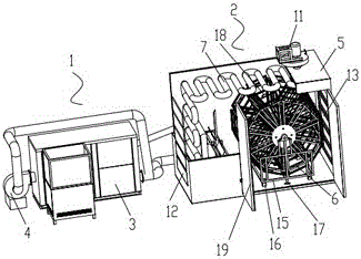
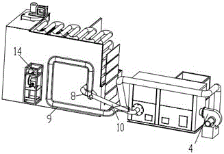
The present invention discloses a rotary wheel type drying system and relates to the technical field of food drying devices. The drying system comprises a biomass hot-blast stove and an oven. An air inlet pipe is connected with an air inlet of a fan, an air outlet of the fan is connected with an air inlet of a hot-blast stove body, a smoke pipe is connected with a chimney outlet of the hot-blast stove body, a free end of the smoke pipe extends into the air inlet pipe, extends out of a free end of the air inlet pipe, and is connected with the chimney inlet of the oven, one end of a chimney coil pipe is connected with the chimney inlet of the oven, the other end of the chimney coil pipe extends outside a shell body, and a hot air outlet of the hot-blast stove body is connected with a hot air inlet of the oven through a hot air pipe. The system utilizes the temperature of the chimney to heat the temperature of the inlet air, uses the chimney coil pipe to heat the interior of the oven, effectively utilizes waste heat energy and has a good energy-saving effect.

Description

technical field [0001] The invention relates to the technical field of food drying devices, in particular to a rotary drying system with good energy-saving effect. Background technique [0002] The dryer has several modes such as belt drying, drum drying, box drying, and tower drying; the heat source includes coal, electricity, gas, etc.; the drying process of materials has hot air flow type and radiation type, etc. , hot air drum drying is that the hot air flow moves forward from the tail, fully contacts with the material, and makes full use of the heat transfer through heat conduction, convection, and radiation; the heat energy is directly transferred to the material, so that the moisture of the material is continuously evaporated in the cylinder, and the material is fed into the cylinder. The air-introduction device at the outlet draws out a large amount of water and wet air to prevent secondary pollution caused by dust discharge; through internal spiral stirring, sweepin...

Claims


Application Information

Patent Timeline
Patent Type & Authority Applications(China)
IPC IPC(8): A23L3/40F26B21/00F26B23/10F26B25/06
CPCA23L3/40F26B21/002F26B23/10F26B25/063Y02P60/85Y02P70/10
Inventor 黄碧义
Owner 黄碧义
Why Eureka
Try Eureka