A laser welding power control device and control method

A laser welding and power control technology, which is applied in the field of laser welding power control and laser welding power control devices, can solve the problems of Raycus lasers being less used, prone to over-burning, and unable to adjust, so as to reduce control costs and avoid over-burning , low cost effect

Active Publication Date: 2018-10-09
FOSHAN HONGSHI LASER TECH CO LTD
View PDF9 Cites 2 Cited by
  • Summary
  • Abstract
  • Description
  • Claims
  • Application Information

AI Technical Summary

Problems solved by technology

[0004] Specifically, the existing mode of controlling the output power of the Raycus laser is mainly the RS232 serial port mode. Due to the limitation of the internal function of the laser (that is, the rise time and fall time of the output power are fixed), the external cannot be adjusted. Therefore, adopt this When this mode is used to control the welding arc starting and terminating power, it is easy to cause overburning. Moreover, using this mode also requires an additional industrial computer and monitor, and the cost is relatively high.
Therefore, the existing Raycus lasers are less used in the field of welding

Method used


Image

  • A laser welding power control device and control method
  • A laser welding power control device and control method
  • A laser welding power control device and control method

Examples


Embodiment Construction

[0027] In order to make the object, technical solution and advantages of the present invention clearer, the present invention will be further described in detail below in conjunction with the accompanying drawings. It is only stated here that the words for directions such as up, down, left, right, front, back, inside, and outside that appear or will appear in the text of the present invention are only based on the accompanying drawings of the present invention, and are not specific to the present invention. limited.

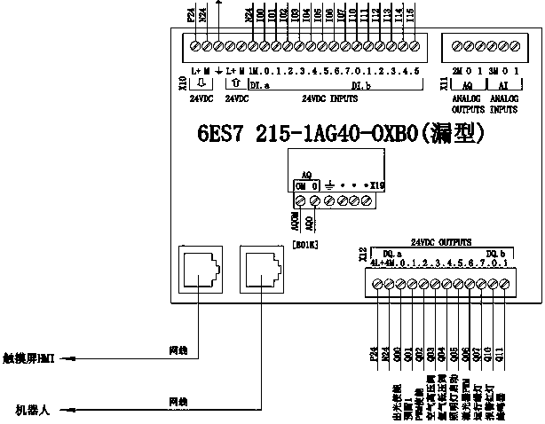
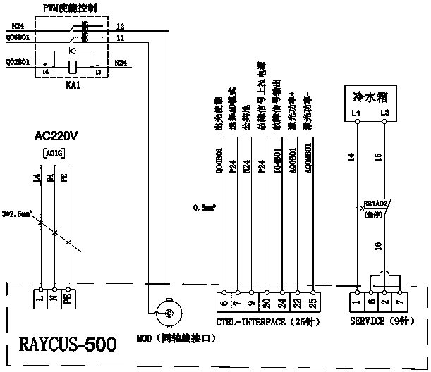
[0028] see figure 1 and figure 2 , figure 1 and figure 2 The specific structure of the laser welding power control device of the present invention is shown, which includes a main controller and a laser connected to the main controller. Specifically, the main controller is provided with an analog voltage output port, a PWM modulation pulse output port and several IO ports, and the main controller is connected to the laser through the analog voltage output po...


PUM


Abstract

The invention discloses a laser welding power control device which comprises a master controller and a laser. The master controller is provided with an analog voltage output port, a PWM modulating pulse output port and a plurality of IO ports. The master controller is connected with the laser through the analog voltage output port, the PWM modulating pulse output port and the IO ports. The invention further discloses a laser welding power control method. The method comprises the steps that the welding power pulse width of the laser within the power increase stage time is adjusted through the master controller, and the welding power pulse width of the laser is sequentially increased within the power increase stage time; and the welding power pulse width of the laser within the power decrease stage time is adjusted through the master controller, and the welding power pulse width of the laser is sequentially decreased within the power decrease stage time. Through the adoption of the laser welding power control device and method, gradual increase and decrease of the PWM pulse width can be effectively adjusted and controlled, the aims of controlling arcing and arc suppression power gradual changing are achieved, and the overburning phenomenon generated when the laser is used for laser welding is effectively avoided.

Description

technical field [0001] The invention relates to the technical field of laser welding, in particular to a laser welding power control device and a laser welding power control method. Background technique [0002] Wuhan Raycus is the first domestic manufacturer capable of independent research and development of fiber lasers. Raycus brand fiber lasers also have high cost performance in the industry and are widely used in the domestic laser cutting industry. [0003] The existing Raycus brand fiber lasers are rarely used in the field of welding technology, because of the particularity of the laser welding process: the arc starting power (increasing light output power) and arc ending power (in the light output falling section) need to be gradually changed and It can be adjusted externally, otherwise, over-burning will occur during arc start or end. [0004] Specifically, the existing mode of controlling the output power of the Raycus laser is mainly the RS232 serial port mode. D...

Claims


Application Information

Patent Timeline
Patent Type & Authority Patents(China)
IPC IPC(8): B23K26/21B23K26/70
CPCB23K26/21B23K26/702
Inventor 常勇李康池
Owner FOSHAN HONGSHI LASER TECH CO LTD
Why Eureka
Try Eureka