A self-tensioning dragging device

A self-tensioning and traction technology, used in transmission, transportation and packaging, elevators in buildings, etc., can solve the problems that hydraulic cylinders cannot achieve equal thrust functions, cannot be used in precise transmission, and take up large space.

Inactive Publication Date: 2017-01-11
北京中蓝华翠科技开发有限公司
View PDF3 Cites 2 Cited by
  • Summary
  • Abstract
  • Description
  • Claims
  • Application Information

AI Technical Summary

Problems solved by technology

[0024] 1. The most common existing push-pull device, hydraulic cylinder system, although the technology is mature and widely used, but it needs to be supplemented with complex and huge hydraulic system, pump station fuel tank, complicated pipelines, etc., plus stroke constraints, and daily A large number of factors such as maintenance and repair of the hydraulic system limit the application of the hydraulic cylinder in many occasions; it also leads to a high cost
In terms of function, the hydraulic cylinder cannot realize the two-way equal thrust function
[0025] 2. The existing hoist form cannot be used in precision transmission due to its inherent side shifting problems, slight changes in upward speed and wear problems.
[0026] 3. The lifting method in the form of an elevator, in order to ensure the traction force and save energy consumption, a counterweight must be added, and the counterweight must be used in the vertical space, so this transmission form cannot achieve traction in a non-vertical direction
[0031] Therefore, the problems existing in the prior art are: in the existing traction device, the required deceleration equipment has a complex structure, takes up a large space, and has a large energy loss, thus causing a large amount of labor, cost, and energy consumption

Method used


Image

  • A self-tensioning dragging device
  • A self-tensioning dragging device
  • A self-tensioning dragging device

Examples


Embodiment Construction

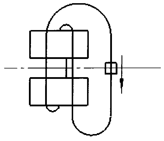
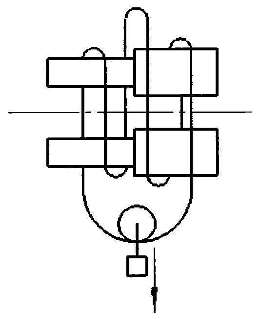
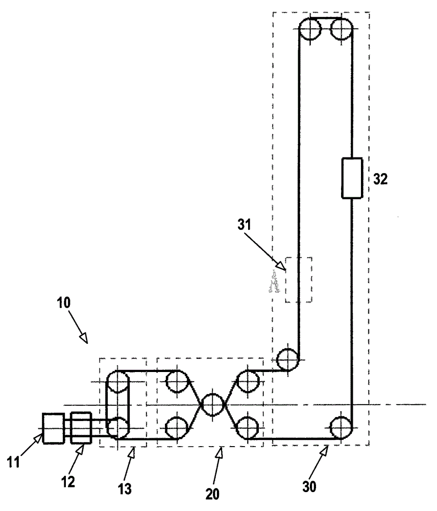
[0069] figure 2 is an overall view of a self-tensioning traction device according to an embodiment of the present invention, which includes a non-differential speed traction mechanism 13 .

[0070] Such as figure 2 As shown, the self-tensioning traction device mainly includes three mechanisms, namely a driving mechanism 10 , a self-tensioning balance mechanism 20 and a traction actuator 30 . The drive mechanism 10 includes a motor 11 , a speed reducer 12 (or a reduction motor) and a non-differential traction mechanism 13 . The non-differential traction mechanism 13 includes two drums 14 arranged side by side and having the same diameter.

[0071] According to the basic principle of traction, it can be known that the non-differential speed traction mechanism 13 can drive the load movement with a certain difference between the steel wire ropes on both sides. Following the mechanism 13 is a self-tensioning balancing mechanism 20 .

[0072] Such as figure 2 As shown, the s...


PUM


Abstract

The invention provides a self-tensioning dragging device comprising a drive mechanism, a self-tensioning balance mechanism and a traction executing mechanism. The drive mechanism comprises a motor, a speed reducer and a dragging mechanism. The self-tensioning balance mechanism comprises a balance shaft with balance guide wheels, a first tensioning guide wheel and a second tensioning wheel, wherein the balance shaft can make linear motion in a linear track between the first tensioning guide wheel and the second tensioning guide wheel. The traction executing mechanism has a bearing connector. A steel wire rope from the dragging mechanism rounds the first tensioning guide wheel and a corresponding balance guide wheel on the balance shaft and enters the traction executing mechanism, and a steel wire rope from the traction executing mechanism is wound to the dragging mechanism after passing the second tensioning wheel and a corresponding balance guide wheel on the balance shaft, so that a closed loop of steel wire ropes; the steel wire rope from the dragging mechanism and the steel wire rope from the traction executing mechanism are wound around the opposite outer peripheral sides of the corresponding balance guide wheels.

Description

technical field [0001] The present invention relates to a self-tensioning traction device for mechanical transmission, and mainly relates to a self-tensioning traction device for outputting large traction force or push-pull force to the outside. , lifting platforms, elevators, etc.), and horizontal traction (such as winches for heavy vehicles), a considerable number of occasions where hydraulic cylinders are used can be used instead of hydraulic cylinders in a reasonable form. Background technique [0002] For the realization of vertical or horizontal traction function, there are relatively mature technical solutions now, and the non-mechanical realization form is the hydraulic cylinder and the auxiliary hydraulic system. The driving structure of mechanical vertical lifting is mainly divided into two categories: one is forced lifting, mainly in the form of drum wire rope, that is, hoist, which is mostly used in mining machinery, hoisting machinery, cranes, etc. The other is...

Claims


Application Information

Patent Timeline
Patent Type & Authority Applications(China)
IPC IPC(8): F16H7/08F16H7/20F16H7/04B66B11/08
CPCF16H7/08B66B11/08F16H7/04F16H7/20F16H2007/0823F16H2007/0842
Inventor 高则行王金伟李维元
Owner 北京中蓝华翠科技开发有限公司
Why Eureka
Try Eureka