Volute air inlet furnace smoke mixing chamber and brown coal boiler including chamber
The technology of mixing chamber and furnace smoke is applied in the field of mixing chamber of a lignite boiler at the smoke outlet of the furnace smoke drying fan pulverizing system, which can solve the problems of cracking on the metal wall and not effectively solving the problem of coking of the lignite boiler. , to achieve the effect of solving coking, coking and cracking problems
- Summary
- Abstract
- Description
- Claims
- Application Information
AI Technical Summary
Problems solved by technology
Method used
Image


Examples
Embodiment
[0025] The specific implementation manners of the embodiments of the present invention will be described below in conjunction with the accompanying drawings.
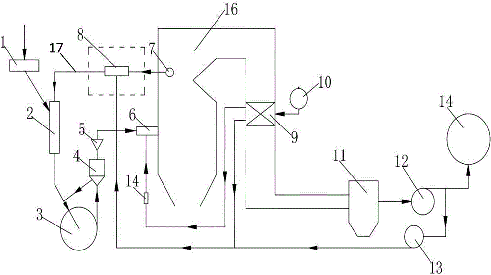
[0026] figure 2 It is a schematic structural diagram of a fan mill three-medium drying direct-blown pulverizing system in an embodiment of the present invention.
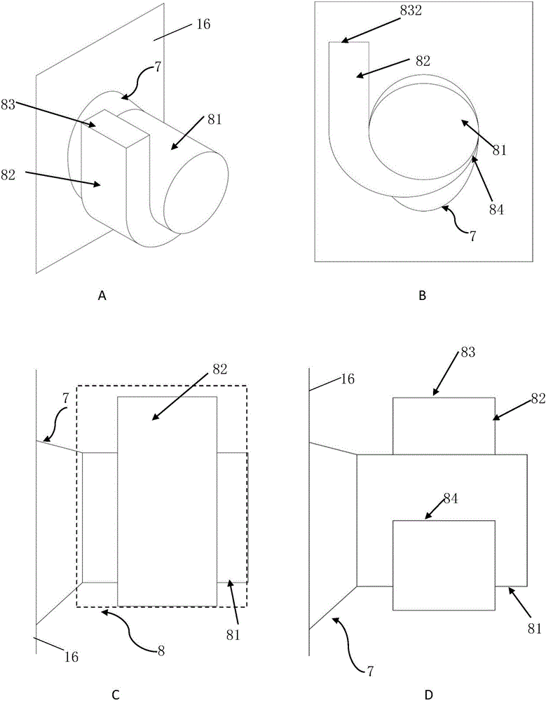
[0027] Such as figure 2 As shown, the fan mill three-medium drying direct-blowing pulverization system includes coal feeder 1, down-flow drying pipe 2, fan coal mill 3, coarse powder separator 4, coal powder distributor 5, burner 6, and furnace smoke outlet 7. Volute intake furnace smoke mixing chamber 8, air preheater 9, blower 10, dust collector 11, induced draft fan 12, cold smoke fan 13, secondary air box 14, chimney 15, lignite boiler 16. The lignite boiler 16 provided in this embodiment includes a furnace smoke exhaust port 7 and a volute intake furnace smoke mixing chamber 8 .
[0028] In the fan mill three-medium drying direct-blown pulverizing s...
PUM
| Property | Measurement | Unit |
|---|---|---|
| Wrap angle | aaaaa | aaaaa |
Abstract
Description
Claims
Application Information