
Missile-borne rudder wing spreading locking mechanism based on pin pusher actuation

A technology of locking mechanism and pusher, applied in the field of servo mechanism, can solve the problems of affecting flight attitude, large space occupied by rudder pieces, influence of strength, etc., and achieve the effect of short wingspan time, compact structure, and satisfying use requirements.

Inactive Publication Date: 2017-01-11
BEIJING RES INST OF PRECISE MECHATRONICS CONTROLS
View PDF5 Cites 23 Cited by
  • Summary
  • Abstract
  • Description
  • Claims
  • Application Information

AI Technical Summary

Problems solved by technology

[0003] For miniaturized rockets, the rudders take up a lot of space compared to the projectile itself, and the performance of the steering gear is easily affected by the external environment. Therefore, the retraction and retraction of the rudders has a great impact on the flight, storage, and transportation of the monomer.
At present, domestic and foreign countries have begun to develop such small guided rockets with wingspan locking function, which basically adopt the form of folding the rudder blades along the outer contour of the cabin: the folded rudder blades take a long time to unfold, which affects the flight attitude of the rocket; The strength of the foldable rudder blades will be affected during the flight, which will also cause a large difference in the performance of the steering gear; at the same time, the asynchrony of the rudder blade deployment is relatively large, which will affect the flight attitude.

Method used


Image

  • Missile-borne rudder wing spreading locking mechanism based on pin pusher actuation
  • Missile-borne rudder wing spreading locking mechanism based on pin pusher actuation
  • Missile-borne rudder wing spreading locking mechanism based on pin pusher actuation

Examples


Embodiment Construction

[0029] In addition to the embodiments described below, the invention can be embodied in other embodiments or carried out in different ways. It is, therefore, to be understood that the invention is not limited to the details of construction of the components described in the following description or shown in the drawings. While only one embodiment is described here, the claims are not limited to that embodiment.

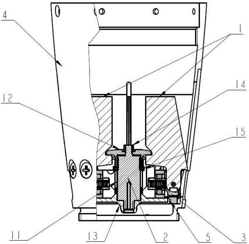
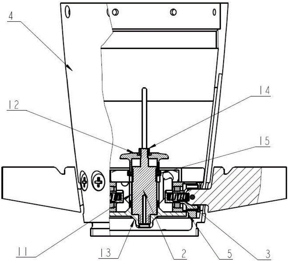
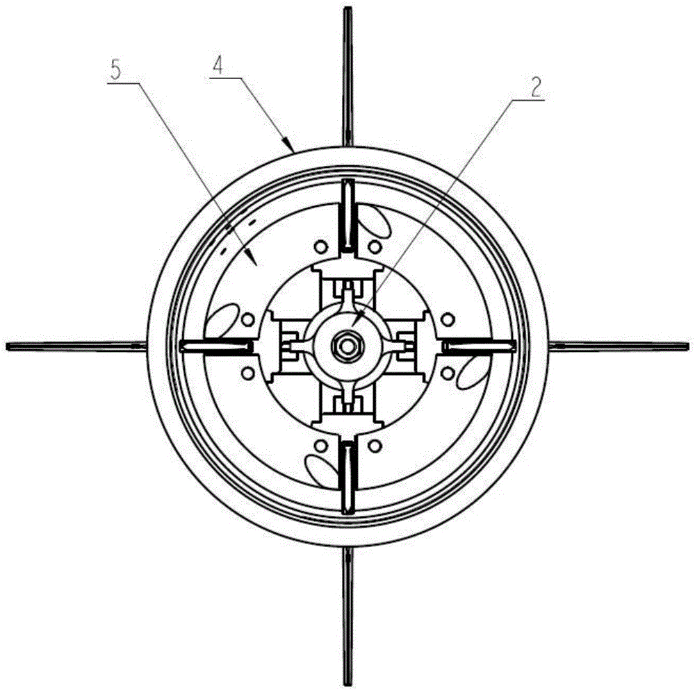
[0030] Such as Figure 1-3 As shown, a rudder blade wingspan locking mechanism based on the action of the pusher includes a rudder blade 1, a wingspan mechanism 2, a rudder shaft assembly 3, a rudder system cabin 4, and a cabin bracket 5; the wingspan mechanism 2 is fixed On the rudder system compartment 4; the rudder blade 1 is installed on the rudder shaft assembly 3, rotates through the pin shaft 32, and is in a tightened and opened state; the wingspan mechanism 2 fixes the rudder blade 1 and simultaneously expands rapidly; the rudder blade and the rudder shaft T...


PUM


Abstract

A scheme that a rudder system with a wing spreading locking function pushes rudder sheets to spread simultaneously and lock the rudder sheets is adopted by the invention. After a rocket projectile is launched, the rudder system is powered by a missile-borne controller; after a rudder spreading command is emitted, the rudder system controller receives the rudder spreading command of the missile-borne control system; current amplification is performed after the rudder system controller receives a rudder spreading command signal, so that a pin pusher is started, and a pushing disc is pushed to spread the four rudder sheets simultaneously; after spreading angles reach 90 degrees, limiting is performed through the locking mechanism, and the whole wing spreading locking function is finished; and then, the missile-borne controller gives a rudder deflecting command, so that a rudder engine is controlled to drive the rudder sheets to swing, and a servo control function is realized. Meanwhile, for ensuring that the sailing posture of the rocket projectile is not affected, the spreading time of the four rudder sheets is very short and the asynchronism of spreading is very low.

Description

technical field [0001] The invention belongs to the field of servo mechanisms, and in particular relates to a locking mechanism for the wingspan locking mechanism of the upper rudder plate of the pusher. Background technique [0002] With the gradual deepening of preparations for modern warfare, the military urgently needs a large number of various types of high-tech precision strike weapons. Among these conventional weapon models, the electric steering gear system has become the technology choice trend of low-power actuators due to its outstanding advantages such as convenient production, debugging, use and maintenance, high cost performance, and high power-to-mass ratio. Therefore, the electric steering gear is being miniaturized and integrated. , multi-functional direction of development. [0003] For miniaturized rockets, the rudders take up a lot of space compared to the projectile itself, and the performance of the steering gear is easily affected by the external envi...

Claims


Application Information

Patent Timeline
IPC IPC(8): F42B10/14F42B10/64
CPCF42B10/14F42B10/64
Inventor 程向丽郭鹏聂振金宁振雷王取
Owner BEIJING RES INST OF PRECISE MECHATRONICS CONTROLS
Learn More