Upper-discrete and lower-annular dual-electrode distributed micro-gyroscope and manufacturing method thereof
A micro gyroscope, distributed technology, applied in gyroscope/steering sensing equipment, gyro effect for speed measurement, instruments and other directions, can solve the problem of different electrode distribution schemes of various micro gyroscopes, etc. The effect of realizing full-angle control and improving detection accuracy
- Summary
- Abstract
- Description
- Claims
- Application Information
AI Technical Summary
Problems solved by technology
Method used
Image
Examples
Embodiment 1
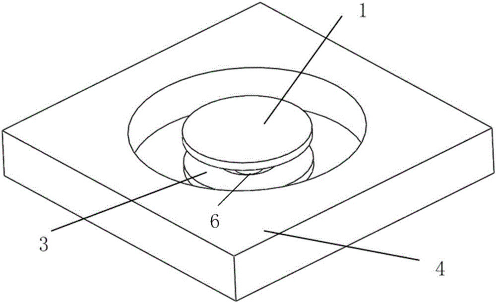
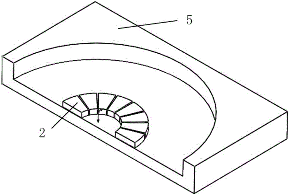
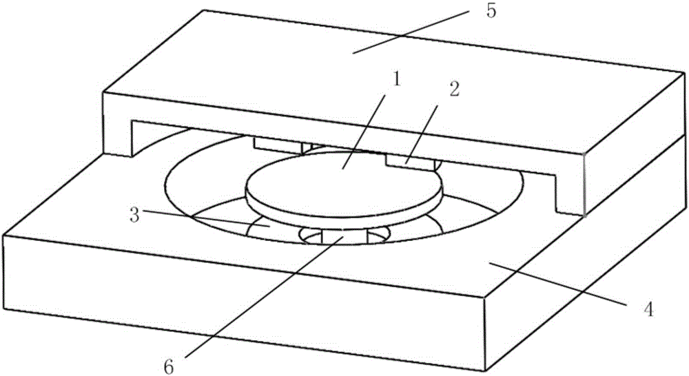
[0047] Such as Figure 1(a)-Figure 1(c) As shown, this embodiment provides an upper discrete and lower ring-shaped dual-electrode distributed miniature disk resonator gyroscope, including:
[0048] A disk-shaped micro-resonator 1;
[0049] Sixteen evenly distributed upper electrodes 2;
[0050] A ring-shaped integrated lower electrode 3;
[0051] A monocrystalline silicon substrate 4;
[0052] a glass substrate 5;
[0053] A central fixed support column 6; wherein:
[0054] One end of the central fixed support column 6 is connected to the monocrystalline silicon substrate 4, and the other end of the central fixed support column 6 is connected to the micro-resonator 1 (as shown in FIG. 1(a));
[0055] Sixteen uniformly distributed upper electrodes 2 are arranged on the surface of the glass substrate 5 (as shown in FIG. 1(b)), and are evenly distributed on the upper side of the micro-resonator 1 (as shown in FIG. As shown in c) ); one of the ring-shaped integrated lower ele...
Embodiment 2
[0067] Such as Figure 2(a)-Figure 2(c) As shown, the present embodiment provides a two-electrode distributed miniature ring resonant gyroscope with an upper discrete ring and a lower ring, including:
[0068] A ring-shaped micro-resonator 1;
[0069] Sixteen evenly distributed upper electrodes 2;
[0070] A ring-shaped integrated lower electrode 3;
[0071] A monocrystalline silicon substrate 4;
[0072] a glass substrate 5;
[0073] A central fixed support column 6; wherein:
[0074] One end of the central fixed support column 6 is connected to the monocrystalline silicon substrate 4, and the other end of the central fixed support column 6 is connected to the micro-resonator 1 (as shown in Figure 2(a)); 16 The uniformly distributed upper electrodes 2 are arranged on the surface of the glass substrate 5 (as shown in Figure 2(b)), and are evenly distributed on the upper side of the micro-resonator 1 (as shown in Figure 2(c) shown); a ring-shaped integrated lower electrod...
Embodiment 3
[0082] Such as Figure 3(a)-Figure 3(c) As shown, the present embodiment provides a dual-electrode distributed miniature multi-ring resonant gyroscope with an upper discrete ring and a lower ring, including:
[0083] A multi-ring micro-resonator 1;
[0084] Sixteen evenly distributed upper electrodes 2;
[0085] A ring-shaped integrated lower electrode 3;
[0086] A monocrystalline silicon substrate 4;
[0087] a glass substrate 5;
[0088] A central fixed support column 6; wherein:
[0089] One end of the central fixed support column 6 is connected to the monocrystalline silicon substrate 4, and the other end of the central fixed support column 6 is connected to the micro-resonator 1 (as shown in Figure 3(a)); 16 The uniformly distributed upper electrodes 2 are arranged on the surface of the glass substrate 5 (as shown in Figure 3(b)), and are evenly distributed on the upper side of the micro-resonator 1 (as shown in Figure 3(c) shown); a ring-shaped integrated lower el...
PUM
| Property | Measurement | Unit |
|---|---|---|
| Radius | aaaaa | aaaaa |
| Thickness | aaaaa | aaaaa |
| Thickness | aaaaa | aaaaa |
Abstract
Description
Claims
Application Information
 - R&D
- Intellectual Property
- Life Sciences
- Materials
- Tech Scout
- Unparalleled Data Quality
- Higher Quality Content
- 60% Fewer Hallucinations
Browse by: Latest US Patents, China's latest patents, Technical Efficacy Thesaurus, Application Domain, Technology Topic, Popular Technical Reports.
© 2025 PatSnap. All rights reserved.Legal|Privacy policy|Modern Slavery Act Transparency Statement|Sitemap|About US| Contact US: help@patsnap.com


