Two-electrode distributed micro-gyroscope with upper discrete and lower ring and its preparation method

A micro-gyroscope, distributed technology, used in gyroscope/steering sensing equipment, gyro effect for speed measurement, instruments, etc. The effect of realizing full-angle control and improving detection accuracy

Active Publication Date: 2020-09-15
SHANGHAI JIAOTONG UNIV +1
View PDF6 Cites 0 Cited by
  • Summary
  • Abstract
  • Description
  • Claims
  • Application Information

AI Technical Summary

Problems solved by technology

[0006] However, the above-mentioned patents only provide the structural scheme of the miniature hemispherical gyroscope with internal discrete electrodes and external discrete electrodes, and cannot provide different electrode distribution schemes for various miniature gyroscopes.

Method used


Image

  • Two-electrode distributed micro-gyroscope with upper discrete and lower ring and its preparation method
  • Two-electrode distributed micro-gyroscope with upper discrete and lower ring and its preparation method
  • Two-electrode distributed micro-gyroscope with upper discrete and lower ring and its preparation method

Examples


Embodiment 1

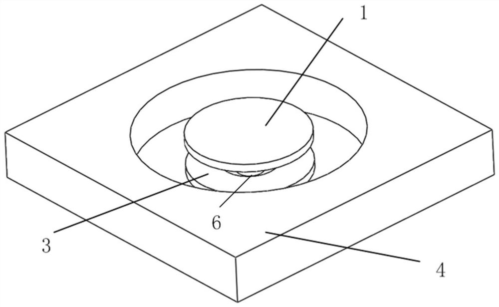
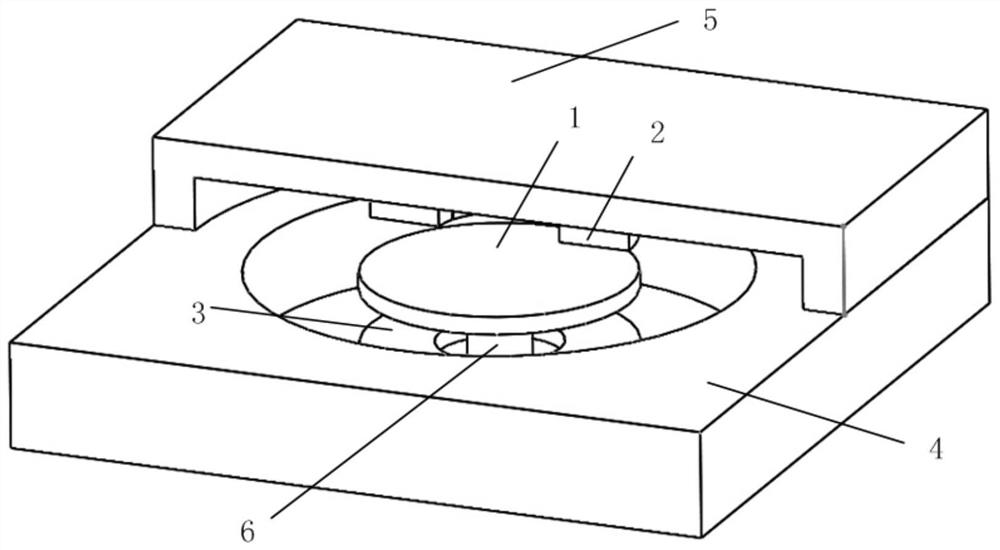
[0047] Such as Figure 1 (a)-Figure 1 (c) As shown, this embodiment provides a two-electrode distributed micro-disk resonant gyroscope with a discrete upper portion and a lower ring shape, including:

[0048] A disc-shaped miniature harmonic oscillator 1;

[0049] Sixteen uniformly distributed upper electrodes 2;

[0050] A ring-shaped integrated lower electrode 3;

[0051] A single crystal silicon substrate 4;

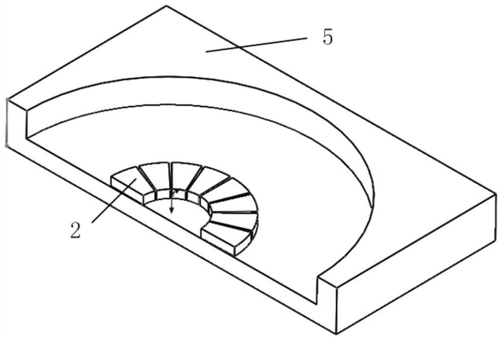
[0052] A glass substrate 5;

[0053] A central fixed support column 6; among them:

[0054] One end of the central fixed support column 6 is connected to the single crystal silicon substrate 4, and the other end of the central fixed support column 6 is connected to the micro resonator 1 (as shown in FIG. 1(a));

[0055] Sixteen of the uniformly distributed upper electrodes 2 are arranged on the surface of the glass substrate 5 (as shown in Fig. 1(b)), and are evenly distributed on the upper side of the micro resonator 1 (as shown in Fig. 1() c) Shown); a ring-shaped integrated low...

Embodiment 2

[0067] Such as Figure 2(a)-Figure 2(c) As shown, this embodiment provides a two-electrode distributed micro ring resonant gyroscope with a discrete upper ring and lower ring, including:

[0068] A ring-shaped miniature resonator 1;

[0069] Sixteen uniformly distributed upper electrodes 2;

[0070] A ring-shaped integrated lower electrode 3;

[0071] A single crystal silicon substrate 4;

[0072] A glass substrate 5;

[0073] A central fixed support column 6; among them:

[0074] One end of the central fixed support column 6 is connected to the single crystal silicon substrate 4, and the other end of the central fixed support column 6 is connected to the micro resonator 1 (as shown in FIG. 2(a)); The uniformly distributed upper electrodes 2 are arranged on the surface of the glass substrate 5 (as shown in FIG. 2(b)), and are evenly distributed on the upper side of the micro resonator 1 (as shown in FIG. 2(c)) As shown); a ring-shaped integrated lower electrode 3 is provided on the surf...

Embodiment 3

[0082] Such as Figure 3 (a)-Figure 3 (c) As shown, this embodiment provides a dual-electrode distributed miniature multi-ring resonant gyroscope with a discrete upper ring and a lower ring, including:

[0083] A multi-ring micro-resonator 1;

[0084] Sixteen uniformly distributed upper electrodes 2;

[0085] A ring-shaped integrated lower electrode 3;

[0086] A single crystal silicon substrate 4;

[0087] A glass substrate 5;

[0088] A central fixed support column 6; among them:

[0089] One end of the central fixed support column 6 is connected to the single crystal silicon substrate 4, and the other end of the central fixed support column 6 is connected to the micro resonator 1 (as shown in FIG. 3(a)); The two uniformly distributed upper electrodes 2 are arranged on the surface of the glass substrate 5 (as shown in FIG. 3(b)), and are evenly distributed on the upper side of the micro resonator 1 (as shown in FIG. 3(c)) As shown); a ring-shaped integrated lower electrode 3 is provid...


PUM

PropertyMeasurementUnit
radiusaaaaaaaaaa
thicknessaaaaaaaaaa
thicknessaaaaaaaaaa

Abstract

The invention provides an upper-discrete and lower-annular dual-electrode distributed micro-gyroscope and a manufacturing method thereof. The micro-gyroscope comprises a monocrystalline silicon substrate, a central fixation supporting column, a micro harmonic oscillator, a plurality of upper electrodes, a lower electrode and a glass substrate. The multiple upper electrodes are uniformly distributed on the upper side of the micro harmonic oscillator, and the lower electrode is arranged on the lower side of the micro harmonic oscillator and is of an annular integrated mode so that the annular integrated lower electrode can be formed. Manufacturing is performed with the combination of MEMS bulk silicon machining and surface silicon machining technologies, different driving and detection modes and different working modes can be provided, and the micro-gyroscope can work in a system needing complex control; driving and detection can be performed by means of the lower electrode and the upper electrodes respectively, the stray capacitance between the driving electrode and the detection electrode can be lowered, and the detection precision can be improved.

Description

Technical field [0001] The invention relates to a micro gyroscope in the field of micro-electromechanical technology, in particular to a two-electrode distributed micro gyroscope with a discrete upper ring and a lower ring shape and a preparation method thereof. Background technique [0002] The gyroscope is an inertial device that can detect the angle or angular velocity of the carrier, and it plays a very important role in the fields of attitude control and navigation and positioning. With the development of national defense technology and aviation and aerospace industries, the requirements of inertial navigation systems for gyroscopes are also developing in the direction of low cost, small size, high precision, multi-axis detection, high reliability, and adaptability to various harsh environments. Therefore, the importance of MEMS micro-gyros is self-evident. In particular, as an important research direction of MEMS micro-gyros, micro-disk resonant gyroscopes have become a re...

Claims


Application Information

Patent Timeline
Patent Type & Authority Patents(China)
IPC IPC(8): G01C19/5691
CPCG01C19/5691
Inventor 张卫平欧彬刘朝阳唐健孙殿竣邢亚亮陈畅崔峰赵万良成宇翔刘瑞鑫
Owner SHANGHAI JIAOTONG UNIV
Why Eureka
Try Eureka