Distributed Computing Network System

A distributed computing and network system technology, applied in the field of distributed computing network systems, can solve the problems of difficult information sharing, high difficulty and cost, and high difficulty, achieving the effects of great compatibility and flexibility, saving manpower, and agile development

Active Publication Date: 2020-03-17
LYNKROS TECH CO LTD
View PDF9 Cites 0 Cited by
  • Summary
  • Abstract
  • Description
  • Claims
  • Application Information

AI Technical Summary

Problems solved by technology

[0002] Since the 1980s, people have begun to use information technology to realize intelligent automatic control of buildings, such as broadcasting and audio systems for specific service functions, IC card management systems, hotel room management systems, energy monitoring and management systems, and specific electromechanical equipment. Air conditioning control system, security system, fire protection system, cold station control system, electricity safety system, etc. However, the problem is that the management and control systems in the existing technology are often not so "intelligent", and more than half of the building automatic control systems can only be realized in The central control room remotely monitors the operating parameters of the building environment and system equipment, and manually starts and stops or adjusts the operating status of electromechanical equipment through the central control man-machine interface
[0004] 1. The measurement and control points of the terminal need to be named for global communication, define physical attributes and define the relationship between each other. When the number of measurement and control points is large, the work of on-site configuration and configuration becomes extremely heavy and difficult; This work can only be carried out after the construction of the building is completed and the mechanical and electrical equipment is in place, and the available construction period is very short, so the time is rushed; when the building layout or functional division changes in the later period, it is difficult for the automatic control system to change flexibly;
[0005] 2. It is difficult to realize real sharing of information between subsystems. In order to realize cross-system information sharing, a new system must be established on the upper layer of several existing systems, which requires reconfiguration and definition of the overall situation. The difficulty and The cost is extremely high, and it does not meet the needs of building control intelligence, informatization, and front-end;
[0006] 3. The automatic control platform is closed and has poor versatility. The control software is often designed individually for individual buildings. Therefore, in the process of system transformation and expansion, it is difficult to implement new control strategies flexibly and simply on the existing automatic control platform.
[0007] 4. Cross-system integration is difficult, the existing automatic control system and platform are poor in versatility, and the software and hardware environment is not friendly, requiring developers to have high IT expertise. The control strategy of the communication system, the control strategy of the fire protection system, and the control strategy of the security system) are often formulated by engineers in various fields (HVAC engineers, fire safety engineers, etc.), which makes it difficult for engineers in various fields to Its formulated control strategy and control logic are transformed into the control software of the automatic control system, which makes it difficult for the functions that each subsystem should realize to be integrated in the existing automatic control system and automatic control platform

Method used


Image

  • Distributed Computing Network System
  • Distributed Computing Network System
  • Distributed Computing Network System

Examples


Embodiment Construction

[0045] The basic structure of the distributed computing network system of the embodiment of the present invention:

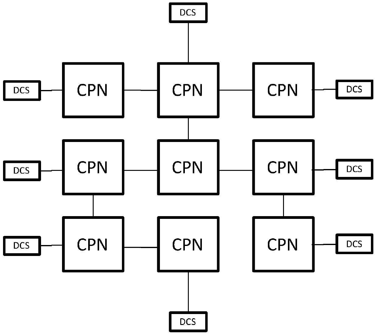
[0046] Such as figure 2 As shown, the structure of the distributed computing network system according to the embodiment of the present invention is shown. The computing network system is composed of several computing nodes (CPN, computing node), and all the computing nodes together form a flat centerless In the computing network, the status of each computing node is equal.

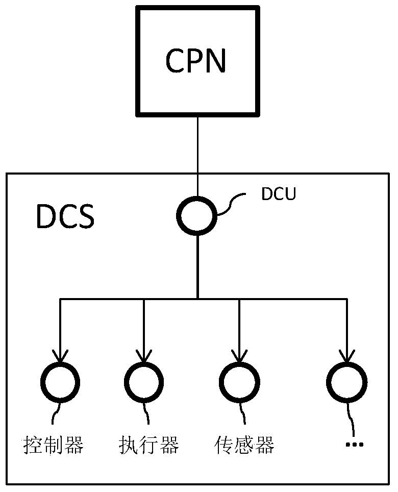
[0047] The computing node is a computer (such as a small computer) with information receiving, processing, and sending functions, and the structure and composition of the computing node are as follows: Figure 5 As shown, each computing node has a processor 1 , a memory 2 and a communication interface 3 .

[0048] Each computing node performs data interaction with its topologically adjacent computing nodes. The data interaction is one-hop communication. After information processing, it th...


PUM


Abstract

The invention discloses a distributed computing network system, which is composed of a plurality of computing nodes (CPN). The CPN are computers having information receiving, processing and transmitting functions. Each CPN conducts data interaction with topologically adjacent CPNs. Each CPN has spatial attributes, wherein the spatial attributes are embodied as the absolute spatial position of the CPN is located and / or the relative spatial position of the CPN in the topological network thereof. The distributed computing network system is provided with an embedded operating system, and at least a portion of the operating system is distributed to each of the CPNs. The operating system provides an API interface used for converting management / control requirements and / or strategies into a standard calculation sequence, and then converting into an instruction sequence that can be identified by the operating system. The CPNs of the distributed computing network system together complete the calculation sequence in the distributed and self-organized manner. The system can be applied to a building automatic control system, and provides an open, flat and easily-programmed control platform.

Description

technical field [0001] The invention relates to the field of computing network systems, in particular to a distributed computing network system with an operating system. Background technique [0002] Since the 1980s, people have begun to use information technology to realize intelligent automatic control of buildings, such as broadcasting and audio systems for specific service functions, IC card management systems, hotel room management systems, energy monitoring and management systems, and specific electromechanical equipment. Air conditioning control system, security system, fire protection system, cold station control system, electricity safety system, etc. However, the problem is that the management and control systems in the existing technology are often not so "intelligent", and more than half of the building automatic control systems can only be realized in The central control room remotely monitors the operating parameters of the building environment and system equip...

Claims


Application Information

Patent Timeline
Patent Type & Authority Patents(China)
IPC IPC(8): G05B19/418
CPCG05B19/418G05B19/41845G05B19/4186
Inventor 姜子炎
Owner LYNKROS TECH CO LTD
Why Eureka
Try Eureka