Satellite-borne circular polarization horn array antenna

An array antenna and circular polarization technology, which is applied in the field of space-borne circular polarization horn array antenna, can solve the problems of limited material selection, small gain of helical antenna, and difficult implementation, and meet the technical requirements of the external environment and improve Effect of radiation efficiency and simple feeding method

Inactive Publication Date: 2017-01-11
TIANJIN JINHANG COMP TECH RES INST
View PDF2 Cites 4 Cited by
  • Summary
  • Abstract
  • Description
  • Claims
  • Application Information

AI Technical Summary

Problems solved by technology

[0004] 1. Since the satellite attitude is not fixed and the wireless signal needs to pass through the atmosphere, it is impossible to use linear polarization signal communication, and circular polarization communication must be used;
[0005] 2. The existing space-borne antennas are mainly helical antennas and reflector antennas. Helical antennas cannot meet the requirements of long-distance communication due to their small gain. Reflector antennas are difficult to implement and costly due to high processing precision requirements for the reflector surface;
[0006] 3. Due to the narrow frequency bandwidth of the existing spaceborne antenna, it cannot meet the requirements of large-capacity data transmission and spread spectrum communication;
[0007] 4. The existing spaceborne antenna is applied outside the cabin, the environmental conditions are high, and the material selection is limited

Method used


Image

  • Satellite-borne circular polarization horn array antenna
  • Satellite-borne circular polarization horn array antenna
  • Satellite-borne circular polarization horn array antenna

Examples


Embodiment Construction

[0036] In order to make the purpose, content, and advantages of the present invention clearer, the specific implementation manners of the present invention will be further described in detail below in conjunction with the accompanying drawings and embodiments.

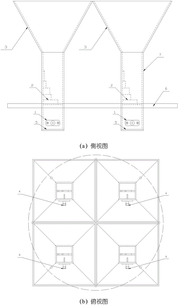
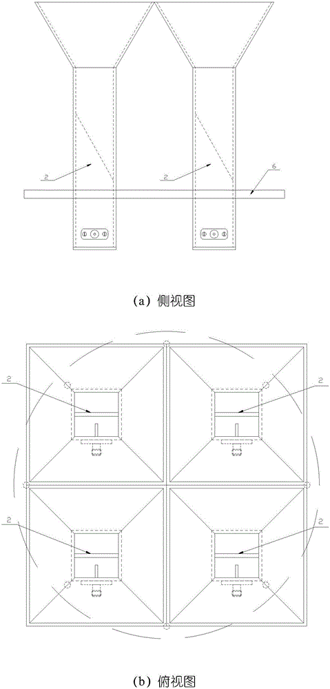
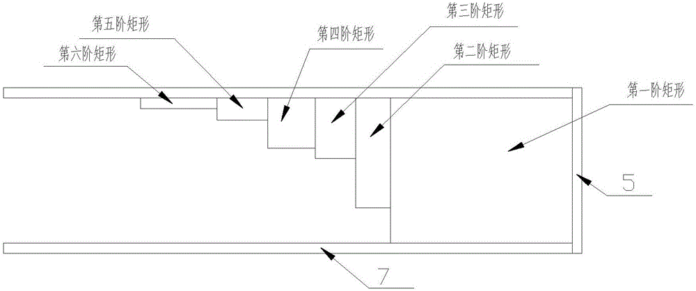
[0037] In order to finally solve the technical problems existing in the prior art, the basic design idea of ​​the array antenna provided by the present invention is: provide a space-borne circularly polarized horn array antenna, and the microwave signal of each space-borne circularly polarized horn array antenna unit is sent from the SMA The feed end of the coaxial feed socket and the SMA coaxial feed socket is fed into the coaxial-waveguide feed end of the antenna unit, and the input TEM mode microwave signal is transformed into a TE mode linearly polarized wave; the input linearly polarized wave has For the TE01 and TE10 modes, for the TE10 mode, the propagation constant from the rectangular waveguide to the partition...


PUM


Abstract

The invention discloses a satellite-borne circular polarization horn array antenna. An SMA coaxial feeder socket (1) comprises an SMA socket body and a through hole, the SMA socket body is mounted on an input variation section of a circular polarizer (2), a feeding probe extends from other surface of the SMA socket body, penetrates into a hollow square waveguide (7) and belongs to a coaxial-waveguide feeding end, the circular polarizer (2) is positioned in the middle of the hollow square waveguide (7), one end of the circular polarizer (2) is connected with the bottom surface of the square waveguide (7), the other end of the circular polarizer (2) is a free end, the height of the circular polarizer (2) is lower than that of the square waveguide (7), the bottom end of a square horn mouth (3) is connected at the top of the free end of the square waveguide (7) and belongs to a beam forming section, a bottom end short circuit board (5) is used for short-circuiting the bottom end of the square waveguide, a mounting bottom board (6) is perpendicular to the square waveguide and used for connecting an antenna unit, and an antenna array is fixed to a star. According to the antenna, the radiation efficiency of the antenna is improved, and light weight is achieved.

Description

technical field [0001] The invention belongs to the technical field of microwave antennas, and relates to a space-borne circularly polarized horn array antenna, which is mainly applied in satellite-to-ground data transmission and communication measurement and control of in-orbit satellites. Background technique [0002] Since the 1960s, satellite communication has developed rapidly and has been widely used in military and civilian applications. Especially in military applications, satellite communication is still its main means of communication, which cannot be replaced by other means of communication. Satellite data transmission and communication measurement and control all rely on space-borne antennas. With the continuous expansion of channel capacity, continuous improvement of transmission rates, and increasingly flexible service methods, the working bandwidth, radiation gain, and beam width of space-borne antennas, etc. The performance index requirements are getting hig...

Claims


Application Information

Patent Timeline
Patent Type & Authority Applications(China)
IPC IPC(8): H01Q1/50H01Q13/02H01Q21/24
CPCH01Q21/24H01Q1/50H01Q13/02
Inventor 董加伟钟玲玲张涛李鹏
Owner TIANJIN JINHANG COMP TECH RES INST
Why Eureka
Try Eureka