Detection method and device for rotor location of permanent magnet synchronous motor

A permanent magnet synchronous motor, rotor position technology, applied in motor control, electronic commutator, AC motor control and other directions, can solve the problem of Hall position sensor rotor position detection failure and other problems

Active Publication Date: 2017-01-11
GUANGZHOU SHIYUAN ELECTRONICS CO LTD
View PDF5 Cites 0 Cited by
  • Summary
  • Abstract
  • Description
  • Claims
  • Application Information

AI Technical Summary

Problems solved by technology

[0004] The embodiment of the present invention provides a method and device for detecting the rotor position of a permanent magnet synchrono

Method used


Image

  • Detection method and device for rotor location of permanent magnet synchronous motor
  • Detection method and device for rotor location of permanent magnet synchronous motor
  • Detection method and device for rotor location of permanent magnet synchronous motor

Examples


Embodiment 1

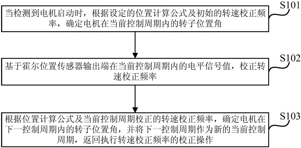
[0019] figure 1 A flow diagram of a method for detecting the rotor position of a permanent magnet synchronous motor provided in Embodiment 1 of the present invention. This method is suitable for real-time detection of the rotor position of a permanent magnet synchronous motor. The detection device is implemented, wherein the detection device can be implemented by software and / or hardware, and is generally integrated on a single-chip microcomputer used in conjunction with a permanent magnet synchronous motor.

[0020] Such as figure 1 As shown, the method for detecting the rotor position of a permanent magnet synchronous motor provided by Embodiment 1 of the present invention includes the following operations:

[0021] S101. When it is detected that the motor starts, according to the set position calculation formula and the initial speed correction frequency, determine the rotor position angle of the motor in the current control period.

[0022] In this embodiment, the contro...

Embodiment 2

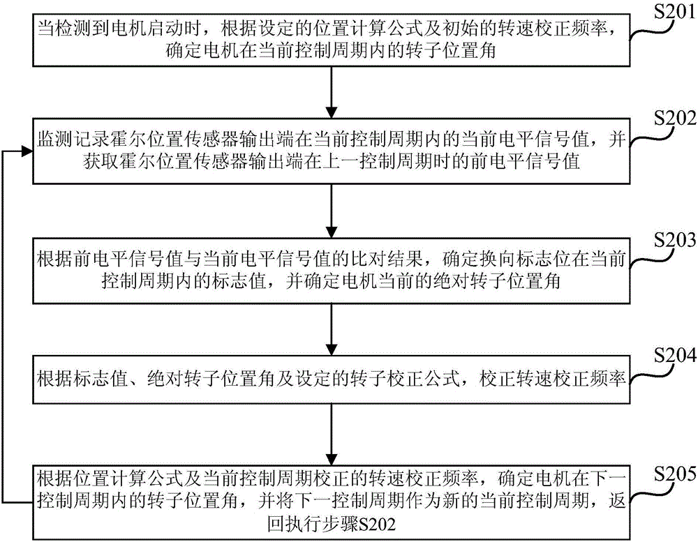
[0035] figure 2 It is a schematic flowchart of a method for detecting the rotor position of a permanent magnet synchronous motor provided in Embodiment 2 of the present invention. Embodiment 2 of the present invention is optimized on the basis of the above-mentioned embodiments. In this embodiment, "correct the rotational speed correction frequency based on the level signal value of the Hall position sensor output terminal in the current control cycle" is further Specifically: monitor and record the current level signal value of the output terminal of the Hall position sensor in the current control cycle, and obtain the previous level signal value of the output terminal of the Hall position sensor in the previous control cycle; according to The comparison result of the previous level signal value and the current level signal value determines the flag value of the commutation flag in the current control cycle, and determines the current absolute rotor position angle of the mot...

Embodiment 3

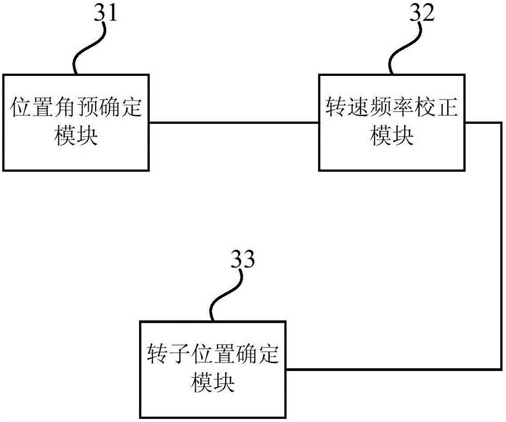
[0059] image 3 It is a structural block diagram of a detection device for the rotor position of a permanent magnet synchronous motor provided in Embodiment 3 of the present invention. The device is suitable for real-time detection of the rotor position of the permanent magnet synchronous motor, wherein the detection device can be realized by software and / or hardware, and is generally integrated on a single-chip computer used in conjunction with the permanent magnet synchronous motor. Such as image 3 As shown, the detection device includes: a position angle predetermined module 31 , a rotational speed frequency correction module 32 and a rotor position determination module 33 .

[0060] Wherein, the position angle pre-determining module 31 is used to determine the rotor position angle of the motor in the current control cycle according to the set position calculation formula and the initial speed correction frequency when the motor is detected to start.

[0061] The rotatio...


PUM


Abstract

The invention embodiment discloses a detection method and a device for the rotor location of the permanent magnet synchronous motor. The method comprises the steps of identifying the rotor position angle of the motor within the current control cycle according to the designed location calculation formula and initial speed correction frequency when detecting the start of the motor; correcting the speed correction frequency based on the level signal value of the output end of the Hall position sensor within the current control cycle; identifying the rotor position angle of the motor within the next control cycle according to the location calculation formula and the corrected speed correction frequency of the current control cycle, and taking the next control cycle as the new current control cycle and returning to conduct the correcting operation of the speed correction frequency. The method can effectively overcome the problem that the detection for rotor location of Hall position sensor becomes invalid when the motor starts, achieving the real-time correct detection of rotor position angle, and the method further enhances the Robustness of the rotor position angle detection to the motor parametric variation significantly.

Description

technical field [0001] Embodiments of the present invention relate to the field of motors, in particular to a method and device for detecting the rotor position of a permanent magnet synchronous motor. Background technique [0002] Permanent magnet synchronous motor (referred to as motor) has the characteristics of high power density, high efficiency, low loss, small size and simple structure, and has been more and more widely used. The superior control performance of permanent magnet synchronous motors requires accurate rotor position information. The traditional rotor position detection is generally realized through the determination of six absolute positions (0°, 60°, 120°, 180°, 240° and 300°) during the motor rotation process by the Hall position sensor within the detection period. The shortcomings of this traditional method are: this method can only accurately determine the 6 absolute positions of the rotor; at the same time, when the motor is just started, the Hall p...

Claims


Application Information

Patent Timeline
IPC IPC(8): H02P6/16H02P25/022
CPCH02P6/16H02P2203/03
Inventor 李云欢
Owner GUANGZHOU SHIYUAN ELECTRONICS CO LTD
Why Eureka
Try Eureka