Wavefront detection method based on Fresnel zone plate

A wavefront detection and strip technology, applied in the field of wavefront sensing, can solve the problems of the optical path length of the wavefront detection system, shorten the optical path length, and overcome the inaccuracy of information detection.

Active Publication Date: 2017-01-18
INST OF OPTICS & ELECTRONICS - CHINESE ACAD OF SCI
View PDF4 Cites 18 Cited by
  • Summary
  • Abstract
  • Description
  • Claims
  • Application Information

AI Technical Summary

Problems solved by technology

In addition, in the field of traditional phase inversion, it is difficult to manufacture large-size glass lenses with small F-number and low aberration, which makes the corresponding wavefront detection system have a long optical path, which is not suitable for the compact and light requirements of the current system.

Method used


Image

  • Wavefront detection method based on Fresnel zone plate
  • Wavefront detection method based on Fresnel zone plate
  • Wavefront detection method based on Fresnel zone plate

Examples


Embodiment

[0039] In an exemplary embodiment of the present invention, a Fresnel zone plate-based wavefront detection method is provided.

[0040] Please refer to Figure 1-8 , the method of this embodiment includes:

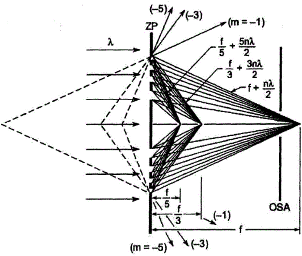
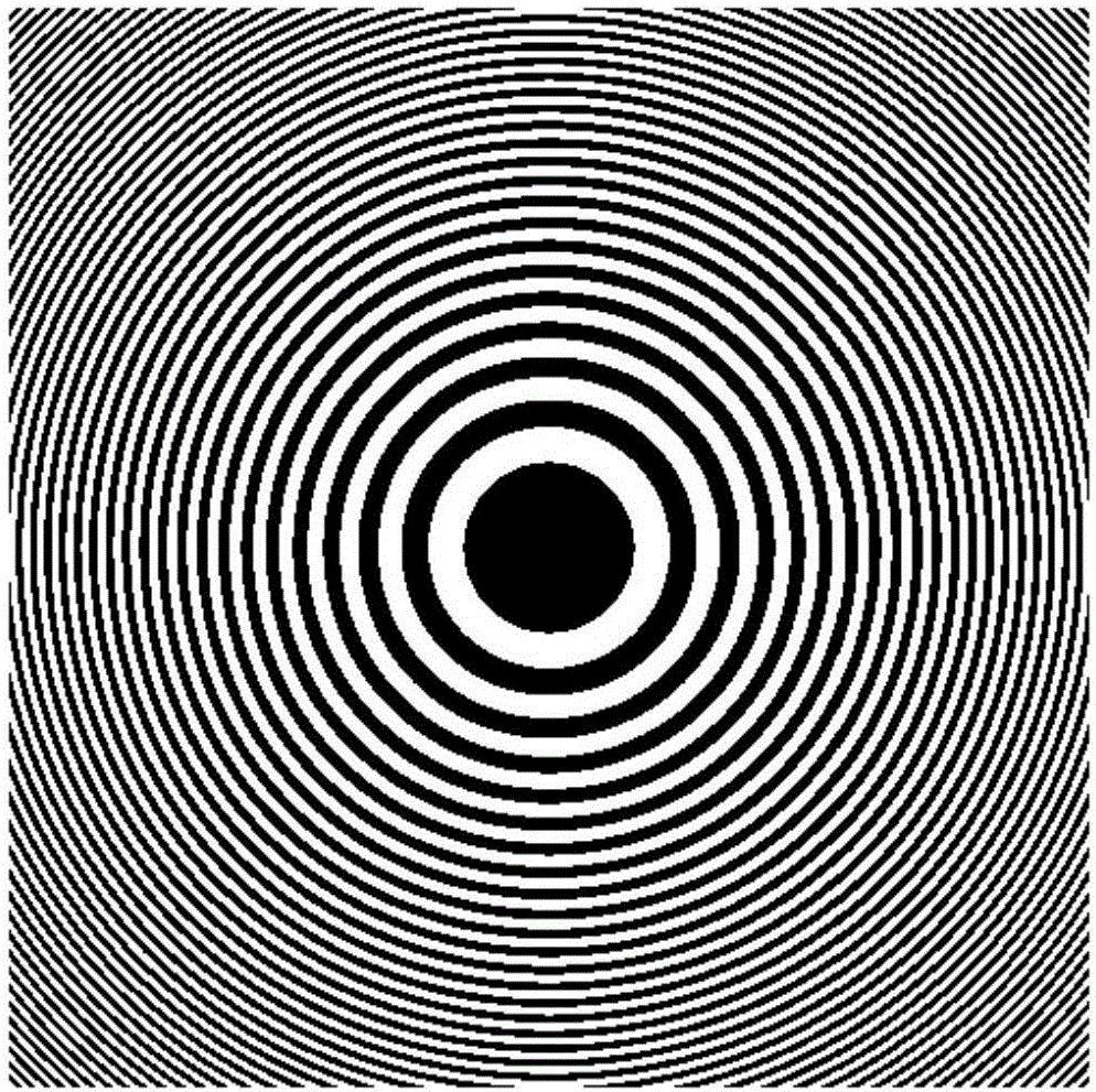
[0041] Prepare a Fresnel zone plate with a focal length of the first focal point of 1000 mm, such as figure 2 As shown, the incident light wavefront phase to be measured in the embodiment is a random wavefront (PV=3.7415rad, rms=0.8082rad) composed of a 65th order Zernike polynomial, as Figure 5 shown. The far-field light intensity distribution through the Fresnel zone plate is as follows: Image 6 shown.

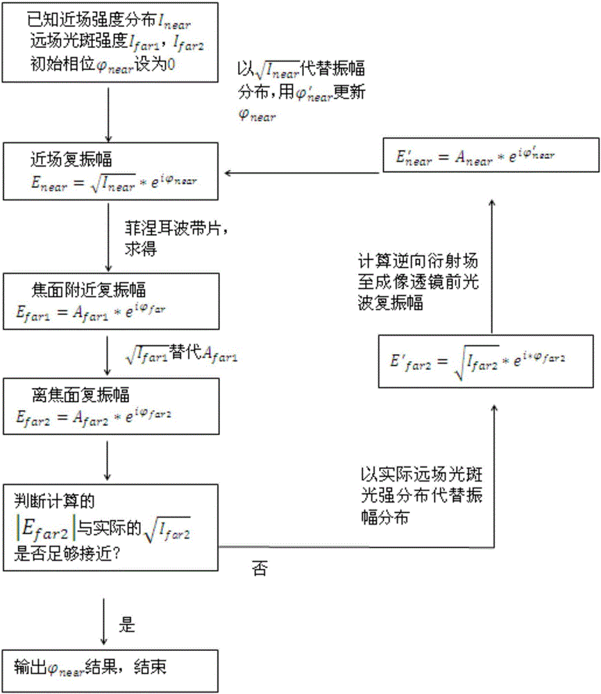
[0042] Step 1: The near-field intensity distribution I of the incident beam is known near and the corresponding light wave image intensity distribution near the focal plane I far1 , the intensity distribution of the light wave image at the out-of-focus plane I far2 , and set the initial value of the near-field wavefront phase distribution in the phase inversion...


PUM


Abstract

The invention provides a wavefront detection method based on a Fresnel zone plate. Distortion wavefront passes the Fresnel zone plate, images are collected at position near the focal plane and far from the focal plane of the zone plate respectively, and an input waveform can be recovered accurately by utilizing the two images as well as the relative defocusing amount therebetween. The Fresnel zone plate belongs to a light and thin focusing element, the length of an optical path can be shortened greatly by utilizing the short focus of the Fresnel zone plate, and the problem that information detection for light spots in the focal plane is not accurate enough under large apertures can be overcome by utilizing the characteristic that the size of light spots near the focal plane is strict and the size of light spots in the focal plane is larger. The method of the invention is suitable for wide-aperture and super-wide-aperture wavefront detection, and has significance in lightweight wavefront inversion.

Description

technical field [0001] The invention relates to a wave front detection method based on a Fresnel zone plate, belonging to the technical field of wave front sensing. Background technique [0002] Phase inversion technology is an important branch of wavefront sensing technology, which is characterized by directly using the collected far-field light wave image information of the beam, and inverting and calculating the near-field wavefront phase distribution information of the beam through the theory of diffraction optics. At present, the thin-film telescopic system is developing rapidly, and developed countries such as Europe and the United States have made it clear that the thin-film telescopic technology is the main way to solve the lightweight and high-resolution of the next generation of ultra-large-aperture space-based space telescopes in the future. Fresnel zone film (see Jerald A.Britten, Shamusundar N.Dixit et al. Large-aperture fast multilevel Fresnel zone lenses ingla...

Claims


Application Information

Patent Timeline
Patent Type & Authority Applications(China)
IPC IPC(8): G01J9/00G02B27/00
CPCG01J9/00G01J2009/002G02B27/00G02B27/0012
Inventor 孔庆峰王帅杨平于信林海奇赖柏衡庞博清谭毅杨康建许冰
Owner INST OF OPTICS & ELECTRONICS - CHINESE ACAD OF SCI
Why Eureka
Try Eureka