Magnetic valve structure for clean tail gas

A solenoid valve and exhaust technology, which is applied in the valve shell structure, lift valve, valve details, etc., can solve the problems of the non-adjustable position of the solenoid valve, increase the processing cost, and the service life of the solenoid valve is not long, so as to ensure the exhaust gas treatment effect, improve Response sensitivity, effect of increasing release time

Inactive Publication Date: 2017-01-25
NINGBO JIANGDONG CHENGCHUANG IND PROD DESIGN CO LTD
View PDF0 Cites 7 Cited by
  • Summary
  • Abstract
  • Description
  • Claims
  • Application Information

AI Technical Summary

Problems solved by technology

Due to the frequent opening and closing of solenoid valves, it often causes severe wear of moving parts, resulting in a short service life of the solenoid valve; in addition, because the position of the static iron core of the existing proportional solenoid valve cannot be adjusted, the Increased assembly size requirements, which in turn increases processing costs
[0004] At present, there is a method in the exhaust gas treatment of automobiles, which is to use the ammonia gas released by solid ammonia to react with the nitrogen oxides in the exhaust gas to form nitrogen gas, thereby controlling the emission of nitrogen oxides. However, when the reaction temperature is too low, the solid ammonia cannot Releases ammonia well, resulting in unsatisfactory exhaust gas treatment

Method used


Image

  • Magnetic valve structure for clean tail gas
  • Magnetic valve structure for clean tail gas

Examples


Embodiment Construction

[0013] The present invention will be described in further detail below in conjunction with the embodiments of the drawings.

[0014] Such as Figure 1 to Figure 2 Shown is a schematic diagram of the structure of the present invention,

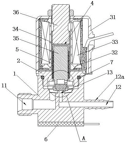
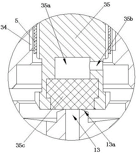
[0015] The reference signs are: valve body 1, air inlet 11, air outlet 12, convex ring 12a, air passage 13, cone 13a, valve cover 2, housing 31, coil support 32, coil 33, sleeve 34 , Moving iron core 35, pressure relief cavity 35a, pressure relief hole 35b, gasket 35c, static iron core 36, magnetic isolation sheet 4, wear sleeve 5, heating sheet 6, sealing ring 7.

[0016] Such as Figure 1 to Figure 2 As shown,

[0017] Based on the structure of a solenoid valve for cleaning exhaust gas, it includes a matching valve body 1 and a valve cover 2. The valve body 1 is provided with an air inlet 11 and an air outlet 12, and air is passed between the air inlet 11 and the air outlet 12 The passage 13 is connected, and the upper part of the valve cover 2 is...


PUM


Abstract

The invention discloses a solenoid valve structure based on cleaning tail gas, which includes a valve body and a valve cover that are matched, an air inlet and an air outlet are opened on the valve body, and the air inlet and the air outlet are connected through an air passage. , the upper part of the bonnet is equipped with an electromagnet assembly, the electromagnet assembly includes a shell, a coil support, a coil wound on the coil support, a sleeve assembled in the center of the coil support, a moving iron core that can move up and down in the sleeve, and a moving iron core fixed on the sleeve. The static iron core at the upper end of the tube, a magnetic isolation sheet is arranged between the static iron core and the moving iron core, a wear-resistant sleeve is arranged between the outer periphery of the moving iron core and the inner wall of the casing, and the lower end of the moving iron core and the The gas passages are matched; the bottom of the valve body is provided with a heating plate. The invention has the advantages of simple structure, long service life and good tail gas treatment effect.

Description

Technical field [0001] The present invention relates to the technical field of solenoid valve manufacturing, in particular to a solenoid valve structure for cleaning exhaust gas. Background technique [0002] A general solenoid valve is composed of an excitation coil, a fixed iron core, a compression spring, a movable iron core, and a valve body. Its working principle is that when the excitation coil is not energized, the sealing head of the fixed iron core will close the valve under the action of the back pressure of the compression spring and the air inlet of the valve. When the excitation coil is energized, the electromagnetic force overcomes the reaction force of the compression spring and the back pressure of the valve air inlet medium, causing the movable iron core to move to the fixed iron core until the two planes attract and the valve is in the open state. [0003] Proportional solenoid valve is a kind of solenoid valve, and its working principle is based on general solen...

Claims


Application Information

Patent Timeline
IPC IPC(8): F16K31/06F16K1/00F16K27/02F16K49/00
CPCF16K31/0655F16K1/00F16K27/029F16K31/0675F16K49/00
Inventor 赵光书
Owner NINGBO JIANGDONG CHENGCHUANG IND PROD DESIGN CO LTD
Why Eureka
Try Eureka