Projection display system and control method thereof

A technology of projection display and control method, which is applied in the field of optics and projection display, and can solve the problems of high cost of red laser, low utilization rate, unfavorable system cost, etc.

Active Publication Date: 2017-01-25
APPOTRONICS CORP LTD
View PDF6 Cites 12 Cited by
  • Summary
  • Abstract
  • Description
  • Claims
  • Application Information

AI Technical Summary

Problems solved by technology

At present, whether it is a transmissive color wheel or a reflective color wheel, if the blue excitation light and the red laser wavelength are combined and then incident on the orange phosphor at the same time, the scheme of combining the red laser and the orange fluorescent etendue will make the red The utilization efficiency of optical laser is not high
Due to the high cost of red laser, the low utilization rate is not good for the cost of the system. Therefore, how to realize a high-efficiency laser-fluorescent light-combining solution applied to the liquid crystal projection system has become an urgent demand.

Method used


Image

  • Projection display system and control method thereof
  • Projection display system and control method thereof
  • Projection display system and control method thereof

Examples


Embodiment 1

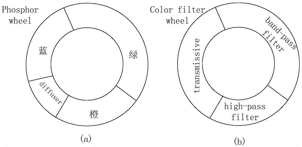
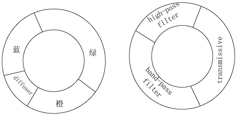
[0062] figure 1 A schematic structural diagram of a projection display device applicable to the control method of the projection display device provided for the implementation of the present invention, in which only the parts related to the embodiment of the present invention are shown, and the unshown parts can refer to the existing projection display device. The projection display device includes a light emitting device 11 capable of emitting sequential light, a light processing device 12 , a liquid crystal light modulation device 13 , a control device 14 and a projection device 15 . The specific projection system for implementing the control method of the present invention is introduced in detail as follows. Obviously, the projection system for realizing the present invention is not limited to the way of example. As in the embodiment, the enumeration of the light source band and the number of color wheel segments does not constitute a limitation of the present invention. For...

no. 1 example

[0068] Figure 5a The implementation process of the control method in the first embodiment of the present invention is shown, the method includes:

[0069] S501. Acquire each primary color image signal in the decoded source image signal.

[0070] The primary color image signals included in the decoded source image signal are generally three primary color image signals, namely red (R) primary color image signal, green (G) primary color image signal and blue (B) primary color image signal.

[0071] S502. Convert the decoded source image signal into a modulation control signal, and use the modulation control signal to control the liquid crystal light modulator Lcos to modulate the time-sequential light.

[0072] Wherein the specific process of converting the decoded source image signal into a modulation control signal and controlling the liquid crystal light modulator Lcos to modulate the sequential light through the modulation control signal is as follows:

[0073]In at least ...

Embodiment 2

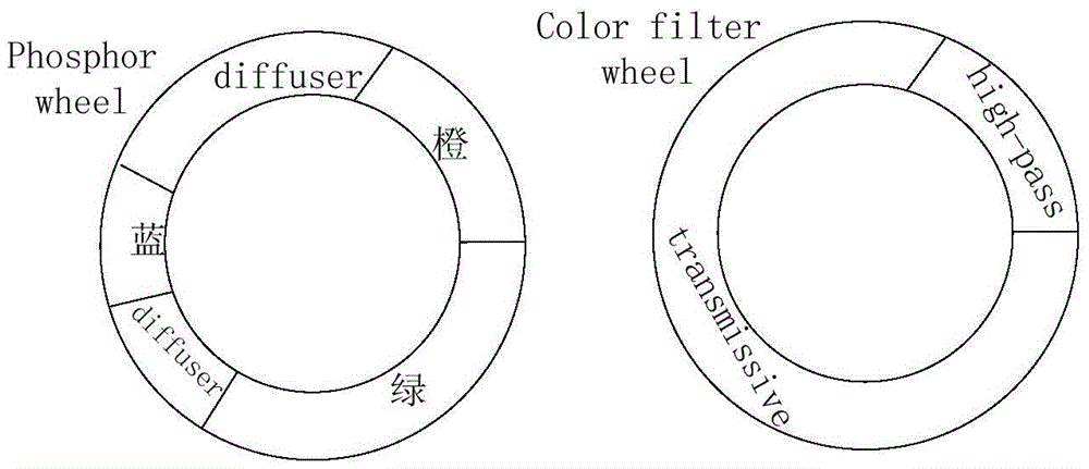
[0091] On the basis of Example 1, the light-emitting device will be further improved, such as Figure 9 As shown, a diffuser section is added to the color wheel structure for transmitting the second laser light, and the light source also includes a laser or a laser module 802b emitting the second laser, and the first laser or the laser module 802a emitted by the first laser and the second laser The second laser light emitted by the laser or the laser module combines light, and the light combining structure may use a dichroic plate 803 ′. The light beam combined by 803 ′ is combined with excitation light again, and the structure 803 of combining light with laser light again refers to Embodiment 1, and will not be described here again. The light beam combined at 803 is processed by the collecting lens 804 and then projected on the color wheel 805 . The downstream of the color wheel 805 is provided with a lens 806 to process the light output of the color wheel 805 .

[0092] Cor...


PUM


Abstract

The invention discloses a control method of a projection display system. The projection display system comprises a liquid crystal light modulation device and a light emitting device capable of emitting time sequence light laser and fluorescent light which have spectrum overlapping. The control method includes: acquiring basic-color image signals in a source image signal after being decoded; converting each basic color image signal in the decoded source image signal into a corresponding basic color modulation control signal, controlling the liquid crystal light modulation device to modulate time sequence light through the basic color modulation control signals; in the process when a first basic color modulates the control signals, modulating laser of time sequence and at least part of fluorescent light by the liquid crystal light modulation device, wherein brightness after spectrum overlapped laser is mixed with fluorescent light is identical with that of corresponding basic color image signals in source image signals after being decoded, and color coordinates after the laser is mixed with the fluorescent light are identical with those of the corresponding basic color image signals in the source image signals after being decoded. In this way, basic-color light which is good in both brightness and color coordinates is acquired.

Description

technical field [0001] The present invention relates to the field of optics, more specifically to the field of projection display. Background technique [0002] At present, spatial light modulators are widely used in the field of projection display. Liquid crystal projection systems represented by LCD and LCOS are applied to various scenes in life due to their low cost and mature technology. Generally, liquid crystal projection systems are divided into single-chip and three-chip types. With the improvement of the performance of liquid crystal devices, especially the improvement of response speed, the performance of liquid crystal devices including ferroelectric liquid crystal and blue-phase liquid crystal (blue-phase liquid crystal) The emergence of single-chip liquid crystal projection systems can be realized. In terms of the light source of the liquid crystal projection system, light bulbs or LEDs are generally used as the light source. The light bulbs have problems of li...

Claims


Application Information

Patent Timeline
Patent Type & Authority Applications(China)
IPC IPC(8): G03B21/20H04N9/31
Inventor 郭祖强胡飞李屹
Owner APPOTRONICS CORP LTD
Why Eureka
Try Eureka