Check patentability & draft patents in minutes with Patsnap Eureka AI!

Method for identifying mutual position relationship of horizontally moving shafts and rotating shaft of multi-axis numerically-controlled machine tool

A CNC machine tool and mutual position technology, which is applied in metal processing machinery parts, measuring/indicating equipment, metal processing equipment, etc., can solve the problems of less research on measurement methods and difficult accuracy detection of multi-axis machine tools, so as to improve the overall processing accuracy. , Accurate identification, improve the effect of measurement accuracy

Inactive Publication Date: 2017-02-01
SOUTHWEST JIAOTONG UNIV
View PDF4 Cites 19 Cited by
  • Summary
  • Abstract
  • Description
  • Claims
  • Application Information

AI Technical Summary

Problems solved by technology

[0005] At present, the geometric error measurement of multi-axis machine tools mainly focuses on the measurement of the geometric error of each single axis, such as the translation axis and the rotation axis. There are few researches on the measurement method of the mutual position relationship between the translation axis and the rotation axis of multi-axis CNC machine tools. Difficult Problems in Testing the Accuracy of Axis Machine Tools

Method used


Image

  • Method for identifying mutual position relationship of horizontally moving shafts and rotating shaft of multi-axis numerically-controlled machine tool
  • Method for identifying mutual position relationship of horizontally moving shafts and rotating shaft of multi-axis numerically-controlled machine tool
  • Method for identifying mutual position relationship of horizontally moving shafts and rotating shaft of multi-axis numerically-controlled machine tool

Examples


Embodiment 1

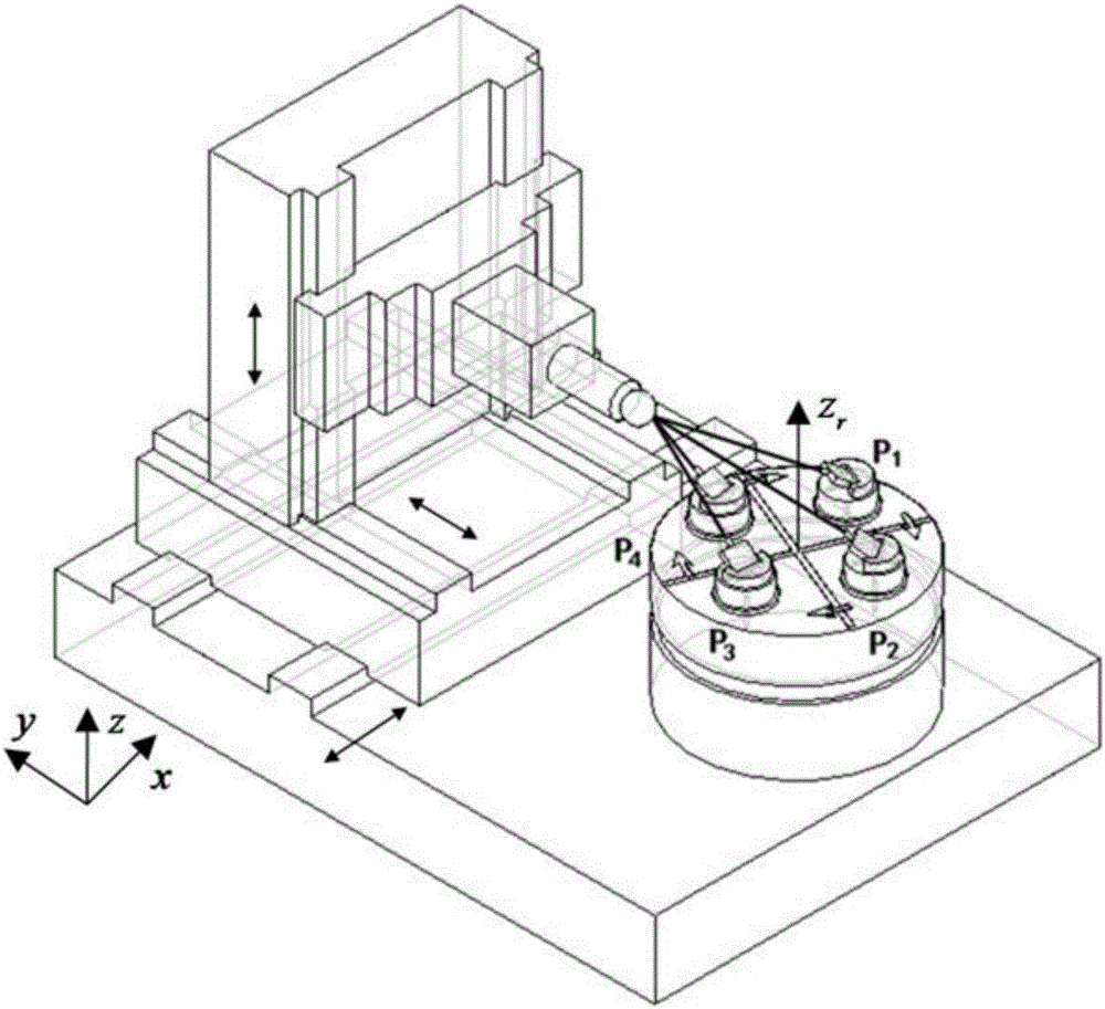
[0113] When measuring, install the cat's eye at a suitable position near the main shaft of the turning and milling machining center, and move with the main shaft. Control the translational parts of the turning and milling machining center to feed in 3D space along the preset path, the movement area is 1200mm×600mm×500mm, and the laser tracker tracks and measures the movement of the translational parts in real time.

[0114] When the translational part is fed along the x, y, and z axes, a measurement point is set for every 100mm of movement, and the total number of measurement points is 87. When the translation component moves to the position of each measurement point, it is controlled to stop for 5 seconds, and the measurement data of the laser tracker at the current position is recorded.

[0115] The first base station position P of the laser tracker on the turntable 1 During the measurement, the translation part is controlled to feed along the preset path, and when the lase...


PUM


Abstract

The invention discloses a method for identifying the mutual position relationship of horizontally moving shafts and a rotating shaft of a multi-axis numerically-controlled machine tool. A laser tracker carries out tracking measurement on the same movement trail of the horizontally moving components on the multi-axis machine tool on a rotary platform of the multi-axis machine tool, and through the space coordinates, obtained through measurement, of measured points, the movement trail of the horizontally moving components and the space coordinates of a series of measured points on the rotary platform are determined; the axis direction vectors generated when the horizontally moving components of the multi-axis machine tool move along the x-axis and the y-axis and the z-r axis direction vectors of the rotating shaft of the rotary platform, and accordingly the mutual position relationship of the horizontally moving shafts and the rotating shaft of the multi-axis machine tool is identified. The method is based on the GPS principle, the influence of angle measurement errors of the laser tracker on overall measurement accuracy is effectively avoided, and the field overall measurement accuracy of the laser tracker is greatly improved. Efficient measurement of the mutual position relationship of the horizontally moving shafts and the rotating shaft is achieved due to the fast measurement advantage of the laser tracker. The method has the advantages of being fast, high in precision and the like.

Description

technical field [0001] The invention belongs to the technical field of laser precision measurement, and in particular relates to a method for identifying the mutual positional relationship between a translation axis and a rotation axis of a multi-axis numerical control machine tool. Background technique [0002] With the rapid development of modern manufacturing industry, high-performance CNC machining technology has become the most important part of modern machinery manufacturing. Multi-axis CNC machine tools, especially five-axis machine tools, are typical high-performance CNC machine tools with the characteristics of high speed, high precision and multi-axis linkage, and are widely used in the processing of various parts. [0003] Due to the inevitable errors in the machining and assembly of multi-axis machine tool parts, there will be certain motion errors in the machine tool movement process, which will eventually affect the machining accuracy of the workpiece. How to ...

Claims


Application Information

Patent Timeline
IPC IPC(8): B23Q17/24B23Q17/22
CPCB23Q17/2428
Inventor 王金栋曾晓涛孙荣康
Owner SOUTHWEST JIAOTONG UNIV
Features
  • R&D
  • Intellectual Property
  • Life Sciences
  • Materials
  • Tech Scout
  • Unparalleled Data Quality
  • Higher Quality Content
  • 60% Fewer Hallucinations
Learn More