Large-temperature-difference heat exchange device for Freon

A heat exchange device and freon technology, applied in the thermal field, can solve problems such as insufficient heat supply, and achieve the effects of reducing high energy consumption, improving heat quality, and improving scientific adjustment capabilities

Inactive Publication Date: 2017-02-01
HIT HARBIN INST OF TECH KINT TECH
View PDF7 Cites 0 Cited by
  • Summary
  • Abstract
  • Description
  • Claims
  • Application Information

AI Technical Summary

Problems solved by technology

[0012] The present invention provides a freon large temperature difference heat exchange device to solve the proble

Method used


Image

  • Large-temperature-difference heat exchange device for Freon
  • Large-temperature-difference heat exchange device for Freon
  • Large-temperature-difference heat exchange device for Freon

Examples


specific Embodiment approach 1

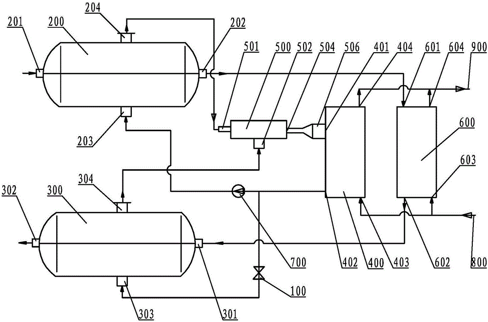
[0028] Specific implementation mode one: combine figure 1Describe this embodiment. This embodiment includes a high-temperature evaporator 200, a low-temperature evaporator 300, a condenser 400, an injector 500, a heat exchanger 600, a throttle valve 100, a Freon pump 700, and a high-temperature water outlet 202 of the high-temperature evaporator 200. It is connected to the heat exchanger water inlet 601 of the heat exchanger 600, the heat exchanger water outlet 602 of the heat exchanger 600 is connected to the low temperature water inlet 301 of the low temperature evaporator 300, and the high temperature water inlet 201 of the high temperature evaporator 200 is connected to the heat network. The water pipe connection, the low temperature water outlet 302 of the low temperature evaporator 300 is connected with the return pipe of the heating pipe network, the high temperature freon steam outlet 204 of the high temperature evaporator 200 is connected with the drive steam inlet 501...

specific Embodiment approach 2

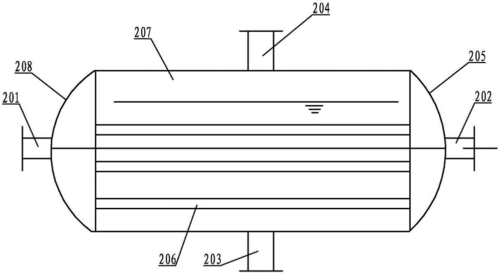
[0029] Specific implementation mode two: combination figure 2 To illustrate this embodiment, the high-temperature evaporator 200 of this embodiment is a horizontal pressure vessel, and its composition includes a high-temperature water inlet 201, a high-temperature water outlet 202, a high-temperature Freon liquid inlet 203, a high-temperature Freon steam outlet 204, a high-temperature right Head 205, high-temperature cylinder 207, high-temperature left head 208 and multiple high-temperature heat transfer tubes 206, high-temperature cylinder 207 is arranged horizontally, the left end of high-temperature cylinder 207 is connected with high-temperature left Connected with the high-temperature right head 205, a plurality of high-temperature heat transfer tubes 206 are arranged horizontally in the high-temperature cylinder 207, the high-temperature water inlet 201 is arranged on the high-temperature left head 208, and the high-temperature water outlet 202 is arranged on the high-te...

specific Embodiment approach 3

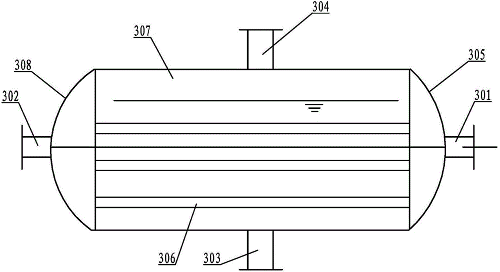
[0030] Specific implementation mode three: combination image 3 Describe this embodiment, the low-temperature evaporator 300 of this embodiment is a horizontal pressure vessel, and its composition includes a low-temperature water inlet 301, a low-temperature water outlet 302, a low-temperature Freon liquid inlet 303, a low-temperature Freon steam outlet 304, a low-temperature right Head 305, low-temperature cylinder body 307, low-temperature left cylinder head 308 and multiple low-temperature heat transfer tubes 306. The low-temperature cylinder body 307 is arranged horizontally. Connected with the low-temperature right head 305, the low-temperature cylinder 307 is horizontally provided with a plurality of low-temperature heat transfer tubes 306, the low-temperature water outlet 302 is arranged on the low-temperature left head 308, and the low-temperature water inlet 301 is arranged on the low-temperature right head 305. The low-temperature Freon steam outlet 304 is arranged a...


PUM


Abstract

The invention discloses a large-temperature-difference heat exchange device for Freon, and relates to a heat engineering technology, and the large-temperature-difference heat exchange device is used for solving the problem that heat supply of newly building a heat supply pipe network or modifying an old heat supply pipe network at present is insufficient. The large-temperature-difference heat exchange device for Freon comprises a high-temperature evaporator, a low-temperature evaporator, a condenser, a heat exchanger, a throttling valve and an Freon pump, wherein a high-temperature water outlet of the high-temperature evaporator is connected with a heat exchanger water inlet of the heat exchanger; a heat exchanger water outlet of the heat exchanger is connected with a low-temperature water inlet of the low-temperature evaporator; a high-temperature Freon steam outlet of the high-temperature evaporator is connected with a drive steam inlet of an ejector; a suction inlet of the ejector is connected with a low-temperature Freon steam outlet of the low-temperature evaporator; a diffuser pipe outlet of the ejector is connected with a condensed steam inlet of the condenser; and a Freon liquid outlet of the condenser is divided into two paths, wherein one path is connected with the low-temperature Freon liquid inlet of a low-temperature evaporator through the throttling valve, and the other path is connected with a high-temperature Freon liquid inlet of the high-temperature evaporator through the Freon pump. The large-temperature-difference heat exchange device is used for newly building the heat supply pipe network or modifying the old heat supply pipe network.

Description

technical field [0001] The invention relates to a thermal technology, in particular to a Freon large temperature difference heat exchange device. Background technique [0002] In recent years, with the continuous development of my country's urban construction, the contradiction between regional development and heating demand has become increasingly prominent. The urban area of ​​all cities is constantly expanding, the large-scale residential areas in the main urban area are constantly increasing, the area of ​​the old urban area is greatly increased every year, and the area of ​​the new urban area is also expanding. Judging from the current heat source and heating network heating capacity of the city, it is far from meeting the needs of the city's rapid development. If the heat supply cannot keep up, it will cause a bottleneck in urban development. In order to solve this contradiction concerning urban development and the vital interests of the people, central heating proje...

Claims


Application Information

Patent Timeline
IPC IPC(8): F24D3/18F25B41/00F25B41/42
CPCF24D3/18F25B41/40Y02B30/12
Inventor 李金峰李伟张雁秋尚德敏
Owner HIT HARBIN INST OF TECH KINT TECH
Why Eureka
Try Eureka