Low-power consumption high-gain low-noise amplifier and operation method thereof

A low-noise amplifier, high-gain technology, applied in the field of high-gain low-noise amplifiers, to achieve the effect of improving gain performance, improving matching stability, and suppressing noise interference

Active Publication Date: 2017-02-01
GUANGXI NORMAL UNIV
View PDF9 Cites 3 Cited by
  • Summary
  • Abstract
  • Description
  • Claims
  • Application Information

AI Technical Summary

Problems solved by technology

[0004] The purpose of the present invention is a low-power high-gain low-noise amplifier and its operating method. The technical problem to be solved is: how to improve the gain performance of the ultra-wideband low-noise amplifier without affecting noise, power consumption and matching performance

Method used


Image

  • Low-power consumption high-gain low-noise amplifier and operation method thereof
  • Low-power consumption high-gain low-noise amplifier and operation method thereof
  • Low-power consumption high-gain low-noise amplifier and operation method thereof

Examples


Embodiment 1

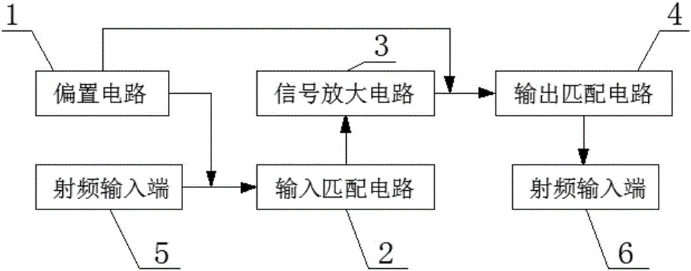
[0037] Such as figure 1 and figure 2 As shown, a low-power high-gain low-noise amplifier includes a bias circuit 1, an input matching circuit 2, a signal amplifying circuit 3 and an output matching circuit 4, and the input matching circuit 2 is connected to a radio frequency input terminal 5, and the input RF signal, carrying out impedance matching to RF signal once; Said signal amplifying circuit 3 is connected with said input matching circuit 2, carries out signal amplification to the RF signal after impedance matching; Said output matching circuit 4 and said signal amplifying circuit 3 connected, the amplified signal is subjected to secondary impedance matching, and the RF signal after secondary impedance matching is output to the RF output terminal 6; the bias circuit 1 is connected to the input matching circuit 2 and the output matching circuit 4 respectively , the bias circuit 1 provides a bias voltage to the input matching circuit 2, and gains the amplified signal; th...

Embodiment 2

[0046] Such as figure 1 and Figure 4 As shown, a low-power high-gain low-noise amplifier includes a bias circuit 1, an input matching circuit 2, a signal amplifying circuit 3 and an output matching circuit 4, and the input matching circuit 2 is connected to a radio frequency input terminal 5, and the input RF signal, carrying out impedance matching to RF signal once; Said signal amplifying circuit 3 is connected with said input matching circuit 2, carries out signal amplification to the RF signal after impedance matching; Said output matching circuit 4 and said signal amplifying circuit 3 connected, the amplified signal is subjected to secondary impedance matching, and the RF signal after secondary impedance matching is output to the RF output terminal 6; the bias circuit 1 is connected to the input matching circuit 2 and the output matching circuit 4 respectively , the bias circuit 1 provides a bias voltage to the input matching circuit 2, and gains the amplified signal; th...

Embodiment 3

[0056] Such as Figure 6 As shown, a method for operating a low-power high-gain low-noise amplifier includes the following steps:

[0057] Step S1. The input matching circuit 2 inputs a radio frequency signal, and performs an impedance matching on the radio frequency signal; the bias circuit 1 provides a bias voltage to the input matching circuit 2;

[0058] Step S2. The signal amplifying circuit 3 amplifies the impedance-matched RF signal; the bias circuit 1 amplifies the amplified signal;

[0059] Step S3. The output matching circuit 4 performs secondary impedance matching on the amplified signal, and outputs the radio frequency signal after the secondary impedance matching to the radio frequency output terminal 6;

[0060] The gain is provided by the bias circuit 1, which can increase the gain of the circuit without increasing the power consumption, save the current generated by the bias circuit 1, and realize the improvement without affecting the noise, power consumption ...


PUM


Abstract

The invention relates to a low-power consumption high-gain low-noise amplifier and an operation method thereof. The amplifier comprises a biasing circuit, an input matching circuit, a signal amplification circuit and an output matching circuit. The input matching circuit inputs radio frequency signals and performs primary impedance matching on the radio frequency signals; the signal amplification circuit performs signal amplification on the radio frequency signals having undergone impedance matching; the output matching circuit performs secondary impedance matching on the amplified signals and outputs the radio frequency signals having undergone the secondary impedance matching; and the biasing circuit provides a bias voltage for the input matching circuit and performs gain on the amplified signals. Compared with the prior art, the low-power consumption high-gain low-noise amplifier saves a current of the biasing circuit, and the circuit gain can be increased under the conditions that power consumption of the circuit is not increased.

Description

technical field [0001] The invention relates to the technical field of radio frequency integrated circuits, in particular to a high-gain low-noise amplifier with low power consumption and an operation method. Background technique [0002] The low-noise amplifier is located at the front end of the receiver and is the first-stage active circuit in the receiver. It needs to amplify the signal from the antenna to suppress various noise interference and improve system sensitivity. To evaluate the performance of a low-noise amplifier, it mainly depends on whether it has a sufficiently low noise figure (NF), good matching performance and stability, etc. [0003] However, the LNAs in the prior art still have deficiencies, such as not being able to achieve low enough power consumption to maintain battery life, reasonable gain, and the like. Contents of the invention [0004] The purpose of the present invention is a low-power high-gain low-noise amplifier and its operating method....

Claims


Application Information

Patent Timeline
Patent Type & Authority Applications(China)
IPC IPC(8): H03F1/00H03F1/56H03F1/42H03F1/26H03F3/16
CPCH03F1/00H03F1/26H03F1/42H03F1/565H03F3/16Y02D30/70
Inventor 宋树祥
Owner GUANGXI NORMAL UNIV
Why Eureka
Try Eureka