High pressure gas filling process

A high-pressure gas filling technology, which is applied to the equipment loaded into the pressure vessel, the installation device of the container structure, gas/liquid distribution and storage, etc., can solve the problems of short life of the sealing ring, leakage, large pressure difference, etc.

Active Publication Date: 2017-02-08
贵州望江气体有限公司
View PDF5 Cites 9 Cited by
  • Summary
  • Abstract
  • Description
  • Claims
  • Application Information

AI Technical Summary

Problems solved by technology

[0004] In the above system, the control plug not only has the function of changing the size of the inner cavity of the gas storage tank, but also plays a sealing role; since the external pressure of the piston is atmospheric pressure, and the internal pressure of the piston needs to withstand the high pressure of compressed natural gas, the pressure on both sides of the piston The difference is extremely large; in order to prevent the leakage of compressed natural gas, the piston needs to have excellent sealing performance. short lifespan and need to be replaced frequently

Method used


Image

  • High pressure gas filling process

Examples


Embodiment Construction

[0028] The present invention will be further described in detail below through specific implementations:

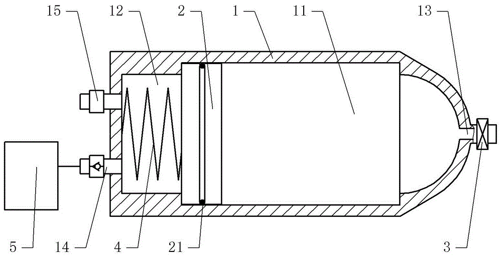
[0029] The reference signs in the drawings of the specification include: tank body 1, compressed natural gas tank 11, air tank 12, air outlet 13, one-way air inlet 14, pressure control valve 15, piston 2, sealing ring 21, exhaust valve 3 , Buffer spring 4, air compressor 5.

[0030] The embodiment is basically like figure 1 Shown:

[0031] The high-pressure gas filling process of this embodiment provides a gas storage tank; the gas storage tank includes a tank body 1, a piston 2 arranged in the tank body 1, and the tank body 1 includes a head end and a tail end. The head end is provided with an air outlet 13 and the air outlet 13 is provided with an exhaust valve 3; the end of the tank body 1 is provided with a pressure control valve 15 and a one-way air inlet 14, and the one-way air inlet 14 is connected to an air compressor 5. Between the piston 2 and the head end of the t...


PUM


Abstract

The patient discloses a high pressure gas filling process, and relates to an exhausting device with structural characteristics as features. A gas storage tank is filled with high pressure gas by adopting the high pressure gas filling process. The gas storage tank comprises a tank body and a piston arranged in the tank body. The tank body comprises a head end and a tail end. A gas outlet is formed in the head end of the tank body. An exhaust valve is arranged at the gas outlet. A pressure control valve and a one-way gas inlet are arranged at the tail end of the tank body. The one-way gas inlet is connected with an air compressor. A compressed natural gas bin is arranged between the piston and the head end of the tank body. An air bin is arranged between the piston and the tail end of the tank body. A seal ring is arranged on the piston. The gas storage tank can ensure constant-flow output of gas. During the processes of gas filling, exhausting and storing, the pressure difference between the air bin and the compressed natural gas bin is always not higher than 1 MPa, so that the service life of the seal ring can be prolonged.

Description

Technical field [0001] The invention relates to an exhaust device characterized by structural characteristics, in particular to a high-pressure gas filling process. Background technique [0002] Compressed natural gas (CNG) refers to natural gas that is dehydrated, filtered, dust-removed, and desulfurized, and then compressed into a gas below 20MPa by a compressor. With the continuous development of automobiles, various hybrid electric vehicles have emerged, among which gas-electric hybrid electric vehicles for the purpose of environmental protection and energy saving have very good development prospects. The gas-electric hybrid vehicle uses the gas released by the high-pressure gas storage tank to perform work and convert it into electric energy or kinetic energy. However, during the use of the gas storage tank, as the gas in the tank decreases, the air pressure in the gas storage tank decreases, and the flow rate of the gas released decreases, thereby reducing the power of the...

Claims


Application Information

Patent Timeline
Patent Type & Authority Applications(China)
IPC IPC(8): F17C5/06F17C13/00F17C13/04
CPCF17C5/06F17C13/00F17C13/04F17C2205/0323F17C2221/033F17C2223/0123
Inventor 钟光岚
Owner 贵州望江气体有限公司
Why Eureka
Try Eureka