Current ripple real-time prediction model-based three-level voltage source variable switching frequency control method

A technology of current ripple and switching frequency, applied in the field of three-level voltage source variable switching frequency control, can solve problems such as loss and current ripple cannot be predicted and controlled, variable switching frequency is blank, and output voltage waveform harmonics are small. , to improve inverter performance, reduce average switching frequency, and reduce peak EMI noise

Inactive Publication Date: 2017-02-08
HUAZHONG UNIV OF SCI & TECH
View PDF2 Cites 31 Cited by
  • Summary
  • Abstract
  • Description
  • Claims
  • Application Information

AI Technical Summary

Problems solved by technology

However, the power electronic converter is not an ideal power conversion device. While realizing power conversion, it faces the following problems: the power electronic converter has switching process and loss. In the high-frequency PWM mode, how to reduce the switching process and loss is a problem. Key issues; the power electronic converter produces a series of pulse waves through PWM technology, which is not a continuous analog source, and the main result is the current ripple of the input and output; the fast switching characteristics of the power electronic converter bring the system High-frequency electrical (voltage, current) excitation, which conducts the analog source and load in the form of electromagnetic interference, thus causing EMI problems
[0003] The most commonly used PWM techniques in current power electronic converters are space vector PWM (SVPWM) and carrier comparison PWM (CBPWM). The switching frequency of traditional PWM technology is fixed. In the existing development,

Method used


Image

  • Current ripple real-time prediction model-based three-level voltage source variable switching frequency control method
  • Current ripple real-time prediction model-based three-level voltage source variable switching frequency control method
  • Current ripple real-time prediction model-based three-level voltage source variable switching frequency control method

Examples


Embodiment Construction

[0035] In order to make the object, technical solution and advantages of the present invention clearer, the present invention will be further described in detail below in conjunction with the accompanying drawings and embodiments. It should be understood that the specific embodiments described here are only used to explain the present invention, not to limit the present invention. In addition, the technical features involved in the various embodiments of the present invention described below can be combined with each other as long as they do not constitute a conflict with each other.

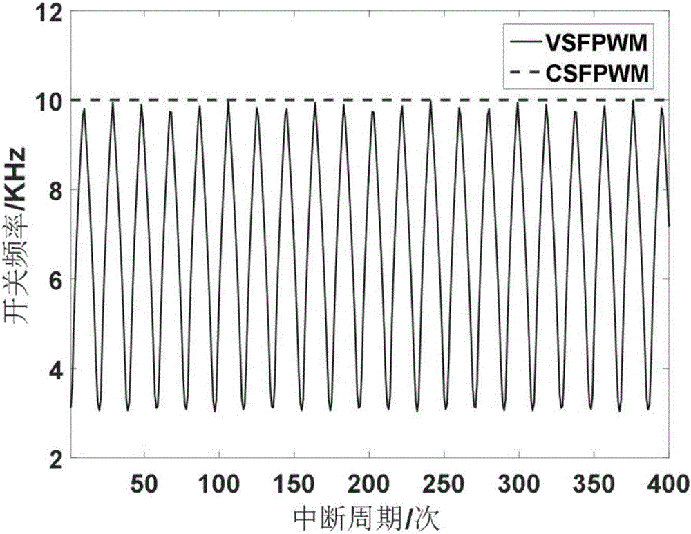
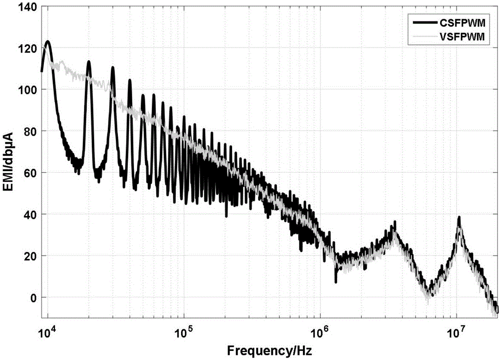
[0036] Aiming at the gaps in the application of variable switching frequency in three-level voltage source inverters, the present invention first establishes a real-time prediction model for general current ripple of three-level inverters. Ripple peak i ripple_max For the control object, to reduce the inverter switching loss and reduce the EMI noise peak.

[0037] The idea of ​​the present inv...


PUM


Abstract

The invention discloses a current ripple real-time prediction model-based three-level voltage source variable switching frequency control method. According to the control method, a current ripple real-time prediction module and a switching cycle updating module are established; and with a current ripple peak value adopted as a control object, the switching cycle of an inverter is updated in real time through using a current ripple real-time prediction model. With the three-level voltage source variable switching frequency control method adopted, the switching frequency of the inverter changes in real time, and therefore, compared with a traditional constant switching frequency PWM control algorithm, the control method of the invention can significantly decrease average switching frequency and greatly reduce the switching loss of the inverter; and since the switching frequency change range of the inverter is wide, spectrum distribution is broader, and a harmonic current peak value can be effectively reduced, and conducted EMI (electro-magnetic interference) can be effectively improved.

Description

technical field [0001] The invention belongs to the field of voltage source variable switching frequency, and more specifically relates to a three-level voltage source variable switching frequency control method based on a real-time prediction model of current ripple. Background technique [0002] Pulse Width Modulation (PWM) technology is the main modulation strategy for current power electronic converters to realize power conversion and control. PWM realizes the output of reference analog quantities through digital pulses. It follows the principle of volt-second balance in a single switching cycle and has a strong high-frequency characteristic. However, the power electronic converter is not an ideal power conversion device. While realizing power conversion, it faces the following problems: the power electronic converter has switching process and loss. In the high-frequency PWM mode, how to reduce the switching process and loss is a problem. Key issues; the power electroni...

Claims


Application Information

Patent Timeline
IPC IPC(8): H02M7/5395H02M1/44
CPCH02M7/5395H02M1/44
Inventor 蒋栋李桥陈嘉楠曲荣海
Owner HUAZHONG UNIV OF SCI & TECH
Why Eureka
Try Eureka