Device for realizing particle suspension and rotation

A particle and shell technology, which is applied in the field of devices for realizing particle suspension and rotation, can solve problems such as difficulty in meeting material processing requirements, affecting processing efficiency, and easily polluting materials, improving product quality, improving suspension ability, and wide application fields. Effect

Active Publication Date: 2017-02-15
HANGZHOU DIANZI UNIV
View PDF8 Cites 12 Cited by
  • Summary
  • Abstract
  • Description
  • Claims
  • Application Information

AI Technical Summary

Problems solved by technology

When processing materials in all directions, it is often necessary to manually move or rotate materials, move or rotate processing equipment, manual operation of easily polluted materials, and m

Method used


Image

  • Device for realizing particle suspension and rotation
  • Device for realizing particle suspension and rotation
  • Device for realizing particle suspension and rotation

Examples


Embodiment 1

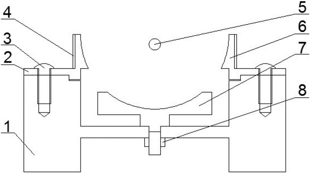
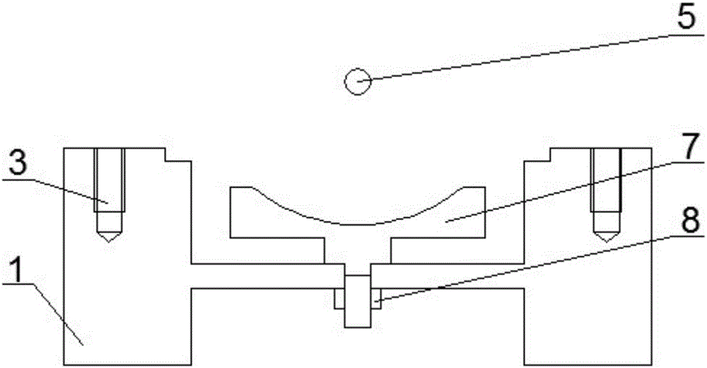
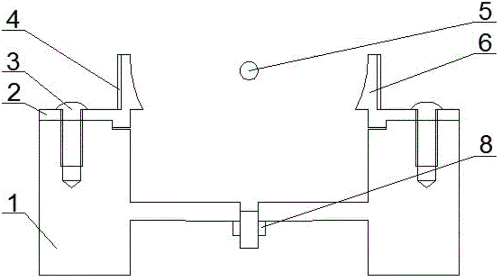
[0036] Such as Figure 1-7 As shown, the device for particle suspension and rotation based on acoustic suspension and rotating sound field in this embodiment includes a base 1, a housing 2, an ultrasonic generator and an ultrasonic reflection end 7. The longitudinal section of the base 1 is an H-shaped structure, and the base is A hollow cylinder, a circular bottom plate 1-1 is fixed on the cross section of the middle of the cylinder, wherein the outer diameter of the circular bottom plate matches the inner diameter of the cylinder. The center of base plate 1-1 forms the installation port that is used to fix ultrasonic reflection end 7, and ultrasonic reflection end 7 is fixedly connected with base plate 1-1 by fixing nut 8 and the upper end of ultrasonic reflection end 7 does not protrude the upper surface of base 1, thereby Fix the ultrasonic reflective end 7 in the base 1, the ultrasonic reflective end 7 has a spherical concave shape, and the spherical concave ultrasonic re...

Embodiment 2

[0041] Such as Figure 8-12 As shown, the device for particle suspension and rotation based on acoustic levitation and rotating sound field in this embodiment includes a base 11, a housing 21, an ultrasonic generator and an ultrasonic reflection end 61, and the base 11 includes a circular platen and a supporting platen The bracket is hollow cylindrical, the outer diameter of the platen is larger than the outer diameter of the bracket, and the structure of the base 11 is axisymmetric. The middle part of the platen is recessed to form an installation opening of the ultrasonic reflection end 61 , and the ultrasonic reflection end 61 is fixedly connected to the top of the base 11 through the fixing nut 71 fixed in the installation opening. The upper surface of the ultrasonic reflection end 61 is spherically concave, wherein the bottom of the concave structure is higher than the upper surface of the base 11 . An ultrasonic generator is arranged directly above the ultrasonic reflec...

Embodiment 3

[0045] The difference between this embodiment and Embodiment 1 is that other even-numbered ring-shaped piezoelectric ceramic sheets are evenly distributed on the outer surface of the ultrasonic traveling wave generator section, which can be adjusted according to the actual requirements for ultrasonic rotating traveling wave parameters. it is good.


PUM


Abstract

The invention belongs to the technical field of ultrasonic machining equipment, and particularly relates to a device for realizing particle suspension and rotation. The device comprises a base, a shell, an ultrasonic generator and an ultrasonic reflection end, wherein the shell is arranged on the base; a piezoelectric ceramic piece unit is arranged on the outer surface of the shell; the ultrasonic reflection end is arranged in the shell; and the ultrasonic generator is arranged over the ultrasonic reflection end. According to the device for realizing particle suspension and rotation based on acoustic suspension and a rotary sound field, particle suspension and rotation are realized through ultrasonic standing wave suspension and rotary traveling waves generated by ultrasonic traveling waves.

Description

technical field [0001] The invention belongs to the technical field of ultrasonic processing equipment, and in particular relates to a device for realizing particle suspension and rotation. Background technique [0002] With the development of technology, the ultra-precision control mechanism has developed into an important component of many high-precision and complex equipment, and its control precision directly determines the required precision during the controlled period. Ultrasonic machining refers to a processing method that applies ultrasonic frequency vibration to a tool or workpiece along a certain direction for vibration processing. Ultrasonic processing system is generally composed of ultrasonic generator, transducer, horn, vibration transmission system, tools, process equipment and other components. The function of the ultrasonic generator is to convert the AC power into an ultrasonic frequency electrical oscillation signal; the function of the transducer is to ...

Claims


Application Information

Patent Timeline
IPC IPC(8): B06B1/06
CPCB06B1/0607
Inventor 吴立群郭佳伟王洪成庄龙翟壮郭亚杰
Owner HANGZHOU DIANZI UNIV
Why Eureka
Try Eureka