A kind of clamping method of compressor blade and used clamp

A compressor and clamping technology, which is applied in clamping, manufacturing tools, positioning devices, etc., can solve the problems of increasing friction coefficient, leaving blank traces, and large processing deformation, so as to reduce waste loss and improve surface quality , Reduce the effect of processing deformation

Active Publication Date: 2019-01-18
CHINA HANGFA SOUTH IND CO LTD
View PDF5 Cites 0 Cited by
  • Summary
  • Abstract
  • Description
  • Claims
  • Application Information

AI Technical Summary

Problems solved by technology

Increased clamping force will cause the part to be clamped and bent
Simply increasing the friction coefficient is not ideal. Therefore, the existing clamping method is likely to cause problems such as large processing deformation, poor profile conformity, and blank traces.
For example, rubber blocks or copper blocks are subject to pressure and friction, and grooves are prone to appear on the surface. At this time, the processed parts are easy to slip into the grooves, causing greater deformation and need to be trimmed
The timing of specific repairs cannot be accurately determined, and effective management and control cannot be carried out

Method used


Image

  • A kind of clamping method of compressor blade and used clamp
  • A kind of clamping method of compressor blade and used clamp

Examples


Embodiment Construction

[0019] In order to have a clearer understanding of the technical features, purposes and effects of the present invention, the specific implementation manners of the present invention will now be described with reference to the accompanying drawings. Wherein, the same parts adopt the same reference numerals.

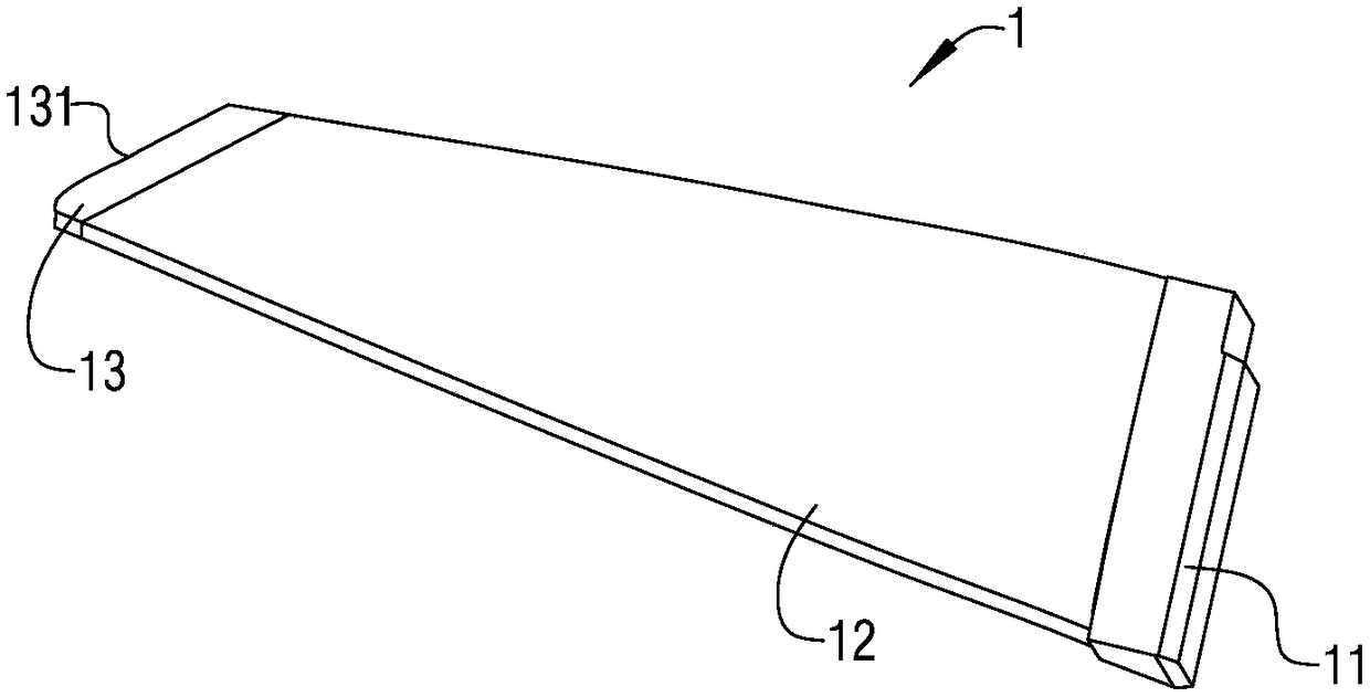
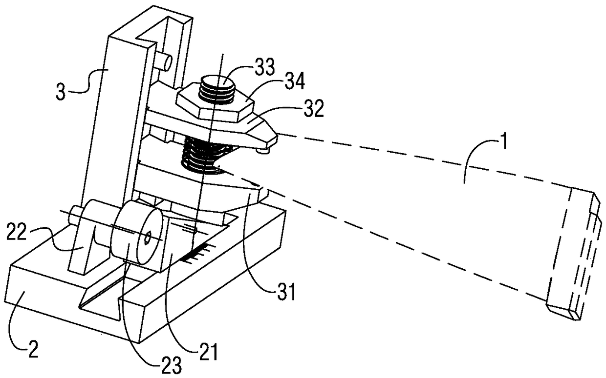
[0020] figure 1 It is a structural schematic diagram of a blank of a compressor blade; figure 2 It is a schematic structural principle diagram of a clamp used in a compressor blade clamping method according to a specific embodiment of the present invention. see figure 1 , figure 2 As shown, the present invention provides a method for clamping a compressor blade, which is used for clamping a blank 1 of a compressor blade. The blank 1 is a forging, including a tenon portion 11 and an airfoil portion 12 and the tip portion 13, which comprises the steps of,

[0021] Step A, during the forging forming process, ensure that the length of the blade tip 13 is 6-8mm;

[002...


PUM


Abstract

The invention provides an air compressor blade clamping method. The air compressor blade clamping method comprises the following steps: step A. ensuring that the length of the tip of the blade is 6-8mm in a forged piece forming process; and step B. providing the clamp to ensure that the tip of the blade is located between a locating plate and a pressing plate, causing the locating plate to contact with the tip of the blade by rotating an eccentric wheel, and causing the pressing plate to clamp the tip of the blade by rotating a nut, thereby completing the clamping of an air compressor blade blank. The air compressor blade clamping method has the beneficial effects that the accurate positioning and clamping of variable positioning surfaces of parts can be realized; the machining deformation is reduced; the quality of molded surfaces of the parts is improved; the loss of waste products is reduced; in addition, the margin range of the molded surfaces can be monitored to explore the machining quality of the part blanks. The invention also provides the clamp for the air compressor blade clamping method.

Description

technical field [0001] The invention relates to the technical field of machining, in particular to a method for clamping a compressor blade and a used clamp. Background technique [0002] figure 1 It is a structural schematic diagram of a blank of a compressor blade, see figure 1 As shown, the blank 1 of the compressor blade part is a forging, which includes a tenon head 11, an airfoil portion 12 and a blade tip portion 13, and the blade airfoil portion 12 needs to be processed by a number of milling processes in subsequent processing. profile processing, after the airfoil profile processing is completed, the blade tip portion 13 is cut and removed to form a blade tip that matches the airfoil profile of the airfoil portion 12 (that is, the final compressor blade The end surface of the airfoil part 12 of the part). [0003] Although the tenon portion 11 is easily clamped by a clamp on the machine tool, since the blank 1 of the compressor blade is relatively long, in order ...

Claims


Application Information

Patent Timeline
Patent Type & Authority Patents(China)
IPC IPC(8): B23Q3/06
CPCB23Q3/063
Inventor 张丽项德义
Owner CHINA HANGFA SOUTH IND CO LTD
Why Eureka
Try Eureka