
Internet of Things based multi-functional live-line detection system and detection method

A live detection, multi-functional technology, applied in the direction of measuring devices, instruments, etc., can solve the problems of strict one-to-one correspondence, large randomness, and many test points, and achieve the effect of reducing management costs, labor intensity, and training costs.

Inactive Publication Date: 2017-02-15
SHANGHAI JUFANG SOFTWARE TECH
View PDF10 Cites 15 Cited by
  • Summary
  • Abstract
  • Description
  • Claims
  • Application Information

AI Technical Summary

Problems solved by technology

However, there are still many problems in the live detection process of electric power equipment: the hand-held live detection equipment used for patrol inspection has a single function, and the patrol personnel need to carry a variety of live detection equipment from different manufacturers to complete the live detection work on site. The efficiency is relatively low; the patrol inspection of power equipment partial discharge usually has many test points, and the test items are not unique. After such a substation or a test line is inspected, there are a lot of test data. During the inspection process, each test is manually recorded. It is difficult to achieve a strict one-to-one correspondence between the information of the test points and the test data, which is not conducive to the collation and reporting of the test data. In addition, the grassroots inspection personnel are very random in recording, and there are big problems in the authenticity and accuracy of the returned data. , which is not conducive to the subsequent analysis of the test data

Method used


Image

  • Internet of Things based multi-functional live-line detection system and detection method

Examples


Embodiment Construction

[0034] The present invention will be described in detail below in conjunction with specific embodiments. The following examples will help those skilled in the art to further understand the present invention, but do not limit the present invention in any form. It should be noted that those skilled in the art can make several modifications and improvements without departing from the concept of the present invention. These all belong to the protection scope of the present invention.

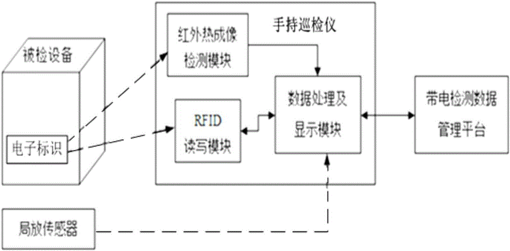
[0035] Such as figure 1 Shown, the present invention is based on the multi-function charging detection system of Internet of Things and comprises:

[0036] Electronic identification, located on the outer surface of the inspected equipment, used to internally solidify the substation name, equipment name, and interval name of the inspected equipment;

[0037] Local sensors, located near or on the body of the device under test, are used to collect partial discharge signals of the device under test; ...


PUM


Abstract

The invention provides an Internet of Things based multi-functional live-line detection system and detection method wherein the system comprises an electronic identifier for solidifying the information and the names of the detected devices therein; a local sensor for acquiring the partial discharge signal of the devices under detection; a handheld inspection instrument for scanning the electronic identifier, reading the information of the detected devices, downloading and completing the live-line tasks as well as processing and displaying the data acquired by the sensor and performing infrared thermal imaging detection to the devices under detection; and a live-line detection data management platform for distributing live-line detection tasks and performing integrated management, analysis and application of the detection data. The local sensor consists of an externally arranged ultrahigh frequency sensor, and etc. The handheld inspection instrument comprises an infrared thermal imaging detection module. The detection system and method of the invention are capable of realizing the management of devices and tasks based on Internet of Things at a reduced cost. And at the same time, it is also possible to perform multi-functional live-line detection jobs, reduce the work intensity of the inspection men and the requirements on the inspection men, and cut the training cost as well.

Description

technical field [0001] The present invention relates to the technical field of electrification detection of electrical equipment, in particular to a multifunctional electrification detection system and detection method based on the Internet of Things. Background technique [0002] Power equipment inspection is a basic work to effectively ensure the safety of power equipment, improve the reliability of power equipment, and ensure the minimum failure rate of power equipment. At present, manual inspections and manual paper media recording are commonly used in China. These methods have defects such as many human factors, high management costs, inability to supervise the work of inspection personnel, and low degree of informatization of inspection data. [0003] Therefore, a kind of inspection system using RFID (radio frequency identification technology) has appeared, such as: the RFID-based power grid equipment inspection device and inspection method disclosed in Chinese Patent ...

Claims


Application Information

Patent Timeline
Patent Type & Authority Applications(China)
IPC IPC(8): G01D21/02
CPCG01D21/02
Inventor 黄成军郭灿新欧阳三元宋方张克勤
Owner SHANGHAI JUFANG SOFTWARE TECH
Learn More