TOF based ranging system and its correction method

A technology of ranging system and transmitting mirror, which is applied in the direction of radio wave measuring system, measuring device, electromagnetic wave re-radiation, etc., can solve the problems of multiple timing steps, high energy density, complicated operation, etc., and achieve the improvement of correction speed and accuracy, Effect of high biosafety and simplified calibration process

Active Publication Date: 2017-02-15
HEBERSON TECH (SHENZHEN) CO LTD
View PDF6 Cites 13 Cited by
  • Summary
  • Abstract
  • Description
  • Claims
  • Application Information

AI Technical Summary

Problems solved by technology

[0003] (1) The accumulated energy density is high, and there is a risk of burns to the skin and eyes; (2) The laser emitter is sensitive to the working temperature and is easily damaged under high temperature conditions, and its luminous intensity and luminous efficiency change with the working temperature Larger; (3) Higher manufacturing cost; (4) Cannot work under strong light environment
[0004] The other is the non-laser solution. Although the cost of this solution is relatively low, there is almost no harm to the human body, and it can work normally at a higher temperature, but because the energy is not easy to concentrate, the measurement distance is relatively short, and it cannot be used under strong conditions. Work in light environment
In addition, the existing distance measurement method has many steps and complex operations when calibrating the measurement distance of the sensor, and requires a high level of operator, which is not convenient for ordinary users to use

Method used


Image

  • TOF based ranging system and its correction method
  • TOF based ranging system and its correction method
  • TOF based ranging system and its correction method

Examples


Embodiment Construction

[0031] The present invention will be described in further detail below in combination with specific embodiments.

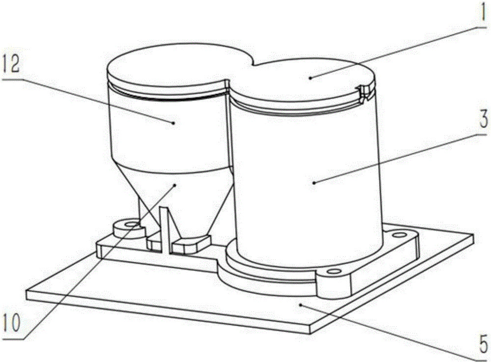
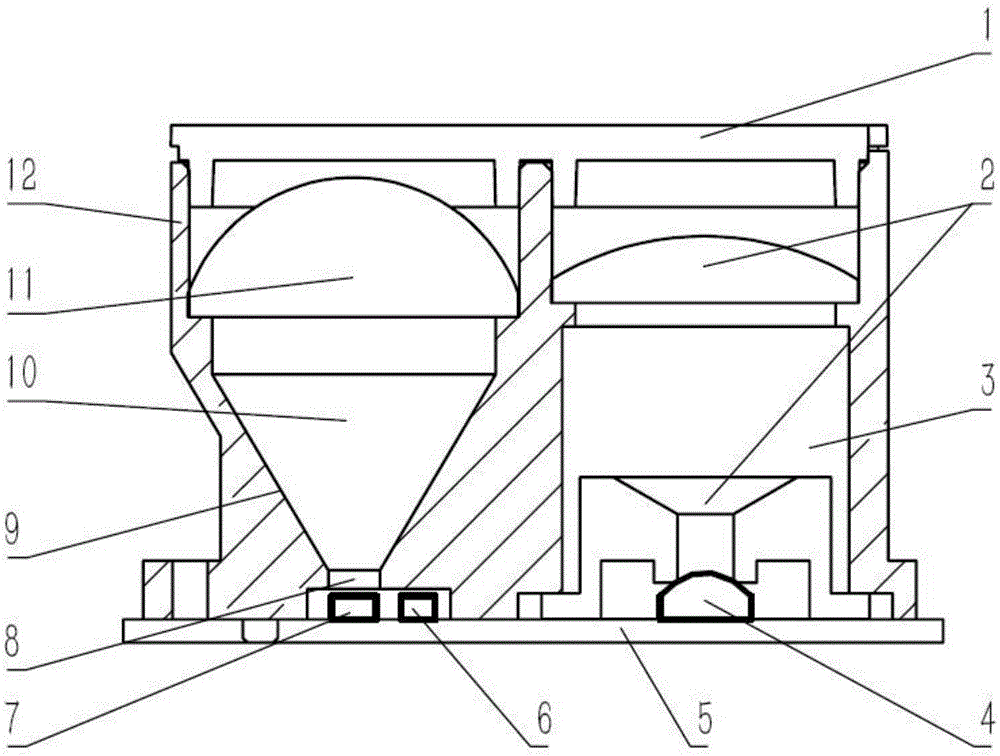
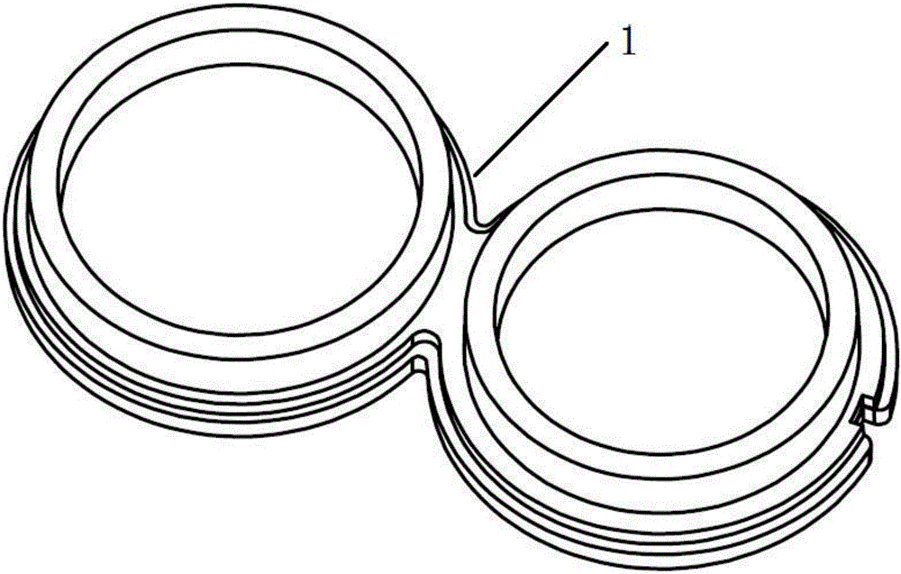
[0032] like Figure 1 to Figure 3 As shown, a distance measuring system based on TOF is disclosed, including a mirror cover 1, a transmitting lens barrel 3, a circuit board 5 and a receiving lens barrel 10, and the transmitting lens barrel 3 and the receiving lens barrel 10 are installed on the circuit board 5 , the mirror cover 1 is used to cover the emitting lens barrel 3 and the receiving lens barrel 10, the emitting lens barrel 3 is provided with a main emitting tube 4 and an emitting focusing lens group 2, and the main emitting tube 4 is installed in the emitting lens barrel On the circuit board, the emission focusing lens group 2 is arranged above the main emission tube 4;

[0033] The receiving lens barrel 10 is arranged side by side with the transmitting lens barrel 3, and the receiving lens barrel 10 includes an anti-stray light structure 9 and a receivi...


PUM


Abstract

The invention discloses a TOF based ranging system and its correction method. A main transmitting tube and a transmitting focusing lens group are arranged inside a transmitting lens barrel. A receiving lens barrel is in parallel arrangement with the transmitting lens barrel; the receiving lens barrel comprises an anti-stray light structure and a receiving focusing lens group. The anti-stray light structure is of a conical structure; the big end part of the conical structure's opening is connected with the receiving focusing lens group while the small end part of the opening is provided with an optical filter. A photosensitive receiving tube and an auxiliary transmitting tube are arranged under the optical filter and both are welded on a circuit board. During the rapid correction of the system, the main transmitting tube does not work, and the auxiliary transmitting tube transmits a beam of modulated infrared light, which is received by the photosensitive receiving tube and is converted into an electric signal. The internal circuit of the circuit board records the phase different between the modulated signal and the photosensitive receiving tube received signal at the time, calculates the ranging distance error at the time, and stores the distance error in a storage device. In this manner, the correction process is completed and compensation can be made to each measurement result.

Description

technical field [0001] The invention relates to a ranging system and a correction method thereof, in particular to a TOF-based ranging system and a correction method thereof. Background technique [0002] At present, there are mainly two types of ranging schemes based on time-of-flight (TOF) technology, one is a laser scheme, and the other is a non-laser scheme. Among them, the laser solution has the advantages of long measurement distance and high accuracy, but the disadvantages are also obvious. The main disadvantages are: [0003] (1) The accumulated energy density is high, and there is a risk of burns to the skin and eyes; (2) The laser emitter is sensitive to the working temperature and is easily damaged under high temperature conditions, and its luminous intensity and luminous efficiency change with the working temperature (3) higher manufacturing cost; (4) unable to work under strong light environment. [0004] The other is the non-laser solution. Although the cost ...

Claims


Application Information

Patent Timeline
Patent Type & Authority Applications(China)
IPC IPC(8): G01S17/08G01S7/481G01S7/497
CPCG01S7/4813G01S7/497G01S17/08
Inventor 吴伟锋王国安周飞丁海鹏孙久春
Owner HEBERSON TECH (SHENZHEN) CO LTD
Why Eureka
Try Eureka