Laser distance measurement method and device

A technology of laser ranging and photodetector, which is applied in measurement devices, radio wave measurement systems, and re-radiation of electromagnetic waves. The effect of fast distance speed, low implementation cost and improved distance measurement accuracy

Inactive Publication Date: 2017-02-15
SHANGHAI INST OF TECHNICAL PHYSICS - CHINESE ACAD OF SCI
View PDF3 Cites 11 Cited by
  • Summary
  • Abstract
  • Description
  • Claims
  • Application Information

AI Technical Summary

Problems solved by technology

[0005] One of the existing methods is to use the sampling frequency much higher than the modulation frequency of the square wave to sample the echo signal and obtain its multiple high-order harmonics through Fourier transform as described in the literature [1], and calculate the fundamental wave and The phase information of the harmonics is then spliced ​​into the final distance measurement result. However, this method requires a sampling rate dozens of times higher than the modulation frequency of the square wave to obtain high-order harmonic components, and it is difficult to apply to the high fundamental frequency of the square wave itself. occasion
[0006] Another method is to use the same square wave signal as the laser output modulation signal and the gating enable signal of the integral echo detector at the same time as proposed in the literature [2], to obtain the integral value output that changes with the target distance, and to use multiple Phase-shifting measurement solves the problem of distance uncertainty, but in principle, this method requires the echo signal and the gating signal to be close to the ideal square wave to achieve high ranging accuracy, and the rise time of the echo signal is demanding when the modulation frequency is high

Method used


Image

  • Laser distance measurement method and device
  • Laser distance measurement method and device

Examples


Embodiment Construction

[0038] The technical solutions in the embodiments of the present invention will be described in detail below in conjunction with the accompanying drawings in the embodiments of the present invention. Obviously, the described embodiments are only some of the embodiments of the present invention, not all of them. Based on the embodiments of the present invention, all other embodiments obtained by persons of ordinary skill in the art without making creative efforts belong to the protection scope of the present invention.

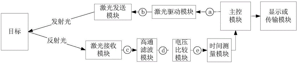
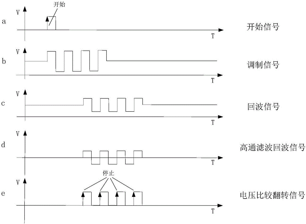
[0039] The system realization example of the method of the present invention is as figure 1 As shown, when a distance measurement starts, the main control module sends a distance measurement start signal to the driving circuit of the laser emission module, and the latter sends a group of modulation signals containing multiple identical square waves to modulate the emitted laser light intensity of the continuous laser, and the target The reflected echo optical s...


PUM


Abstract

The present invention discloses a laser distance measurement method and device. The method comprises: emitting laser signals having light intensity modulated by semi-continuous period square wave; receiving echo optical signals reflected by a target and employing a photoelectric detector to convert the echo optical signals to electric signals; filtering low-frequency components of the electric signals through high-pass filtering, and moving the voltage neutral point modulated by the square wave to a zero point to solve the interference of the echo amplitude variation in the distance measurement; inputting the signals mentioned above to a voltage comparison module to obtain a plurality of overturning signals; and measuring the time difference from the beginning of the distance measurement to each overturning signal, obtaining multiple measurement results of the flight time of the semi-continuous square wave optical signals after each time difference is corrected according to the square wave signal period, and obtaining the accurate distance information after average. The laser distance measurement method has no ranging limitation and has fast laser distance speed and simple realization, can fully utilize the performance advantages of the laser under the square wave modulation, and can construct high-performance and multi-channel laser distance measurement system.

Description

[0001] Technical field: [0002] The invention relates to the field of laser ranging signal processing, in particular to a laser ranging method and system based on multiple time-of-flight measurements under light intensity semi-continuous square wave modulation. [0003] Background technique: [0004] Laser ranging is a major aspect of the application of laser technology. Due to the advantages of high coherence, directivity, and monochromaticity of laser, the laser ranging system can realize long-distance and high-precision ranging functions. The laser ranging system is mainly divided into two types: pulsed light ranging and continuous light ranging. The latter mostly modulates the continuously emitted optical signal and extracts the distance information from the collected echo signal. In the continuous light modulation laser ranging system, higher modulation frequency and laser power can effectively improve the ranging accuracy and ranging speed, but limited by the existing la...

Claims


Application Information

Patent Timeline
Patent Type & Authority Applications(China)
IPC IPC(8): G01S17/10
CPCG01S17/08G01S17/10
Inventor 吴小可徐卫明舒嵘肖琳
Owner SHANGHAI INST OF TECHNICAL PHYSICS - CHINESE ACAD OF SCI
Why Eureka
Try Eureka