Vacuum suction-casting forming process for temperature measuring layer of thermal-insulation container

A thermal insulation container and vacuum suction technology, which is applied in the direction of household components, household appliances, and other household appliances, can solve problems such as inconvenience, damage to the thermal insulation structure of the thermal insulation container, and difficulty in fixing chips reliably, so as to reduce requirements and increase temperature measurement speed Effect

Inactive Publication Date: 2017-02-22
张国清
View PDF6 Cites 0 Cited by
  • Summary
  • Abstract
  • Description
  • Claims
  • Application Information

AI Technical Summary

Problems solved by technology

[0002] Insulation containers play an important role in the logistics cold chain. In the traditional cold chain management, only external profile temperature measuring instruments test the temperature of the insulated container. On the one hand, it is inconvenient; Temperature, if a temperature measuring chip can be embedded in the thermal insulation container, it will help to promote the refined management of the cold chain, but the thermal insulation container generally has a specific thermal insulation structure. If the chip is forcibly embedded, the original thermal insulation structure of the thermal insulation container may be destroyed , and the thermal insulation container is often subject to bumps and vibrations during logistics and transportation. Conventional chip fixing methods are difficult to fix chips reliably. How to solve these problems is a research direction
[0003] Thin-walled thermal insulation containers have thinner walls, making it more difficult to implant chips. How to safely and reliably implant temperature measurement chips on thin-walled thermal insulation containers is also a problem that needs to be solved.

Method used


Image

  • Vacuum suction-casting forming process for temperature measuring layer of thermal-insulation container
  • Vacuum suction-casting forming process for temperature measuring layer of thermal-insulation container

Examples


Embodiment Construction

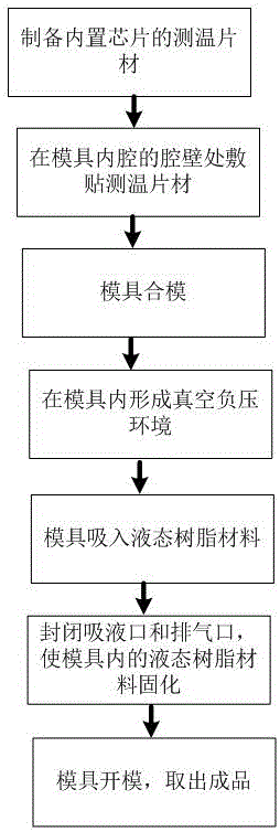
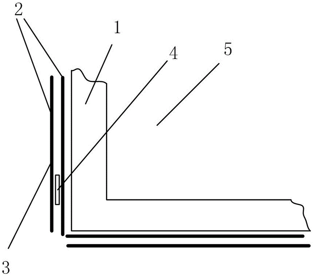
[0028] Such as figure 1 , 2 As shown, a temperature-measuring layer vacuum suction molding process of a thermal insulation container is used to form a surface layer with a temperature-measuring chip 4 at the thermal insulation container 1. The mold of the mouth comprises the following steps in turn.

[0029] A1. Cover the chip 4 with several raw material sheets 2 to make a temperature measuring sheet 3 .

[0030] A2. Apply the temperature measuring sheet 3 and the raw material sheet 2 on the cavity wall of the inner cavity of the mold.

[0031] A3. The mold is closed to form a vacuum negative pressure environment in the mold.

[0032] A4. Vacuum-introduce liquid epoxy resin and unsaturated resin into the mold where the sheet is applied.

[0033] A5. Close the liquid suction port and the exhaust port, and solidify the liquid resin material in the mold to form a thermal insulation container. The cured resin material of the temperature measuring sheet 3 and the raw material s...


PUM


Abstract

The invention discloses a vacuum suction-casting forming process for a temperature measuring layer of a thermal-insulation container, and the vacuum suction-casting forming process is used for forming a surface layer with a temperature measuring chip at the thermal-insulation container. The vacuum suction-casting forming process adopts a mould with a liquid suction hole and a gas exhaust hoe; the forming process sequentially comprises the steps of preparing temperature measuring sheets, applying sheets, carrying out injection-molding production and the like; the temperature measuring sheets are prepared by arranging the temperature measuring chip between two layers of raw material sheets; the injection-molding process adopts a vacuum suction-casting process; and the temperature measuring sheets are embedded into the thermal-insulation container in an injection-molding process. According to the vacuum suction-casting forming process disclosed by the invention, the temperature measuring chip is embedded into the thin-wall thermal-insulation container in a reliable fixing mode while the original thermal-insulation structure of the thermal-insulation container is not damaged.

Description

technical field [0001] The invention relates to the field of heat preservation equipment, in particular to a vacuum suction casting molding process for a temperature measuring layer of a heat preservation container. Background technique [0002] Insulation containers play an important role in the logistics cold chain. In the traditional cold chain management, only external profile temperature measuring instruments test the temperature of the insulated container. On the one hand, it is inconvenient. Temperature, if a temperature measuring chip can be embedded in the thermal insulation container, it will help to promote the refined management of the cold chain, but the thermal insulation container generally has a specific thermal insulation structure. If the chip is forcibly embedded, the original thermal insulation structure of the thermal insulation container may be destroyed , and insulated containers are often subject to bumps and vibrations during logistics and transporta...

Claims


Application Information

Patent Timeline
Patent Type & Authority Applications(China)
IPC IPC(8): B29C39/10B29C39/42B29L31/00
CPCB29C39/10B29C39/42B29L2031/712
Inventor 张国清张漫莉张慧娴
Owner 张国清
Why Eureka
Try Eureka