

Seeding and shoulder expanding device and technique for single crystal rods and single crystal furnace
A single crystal rod and single crystal furnace technology, which is applied in the field of single crystal silicon manufacturing, can solve the problems of not ensuring stable temperature change, delay and oscillation, increasing seeding and shoulder placement time, etc.
- Summary
- Abstract
- Description
- Claims
- Application Information
AI Technical Summary
Problems solved by technology
Method used
Image

Examples
Embodiment 1
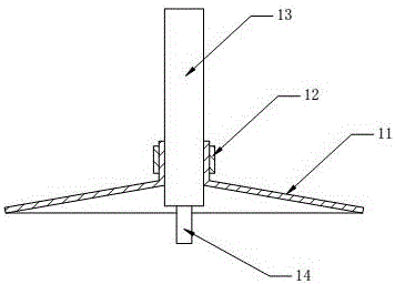
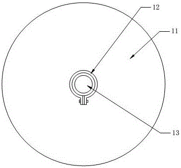
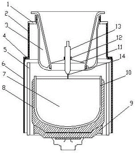
[0032] Example 1: A polished molybdenum sheet with an outer diameter of 175 mm and an included angle of 180 degrees, 300 mm away from the surface of the silicon liquid, was installed on the weight of a Shangyu 100 single crystal furnace; The seeding length is 180mm; the rotation speed of the shouldered crucible is 10rpm, the rotation speed of the seed crystal is 10rpm, and the pulling speed of the shoulder is 0.8mm / min.
Embodiment 2
[0033] Example 2: A polished molybdenum sheet with an outer diameter of 205 mm and an included angle of 180 degrees, 300 mm away from the surface of the silicon liquid, was installed on the weight of a Shangyu 100 single crystal furnace; the seeding crucible rotated at 10 rpm and the seed crystal at 12 rpm. The seeding length is 180mm; the rotation speed of the shouldered crucible is 10rpm, the rotation speed of the seed crystal is 10rpm, and the pulling speed of the shoulder is 0.8mm / min.
Embodiment 3
[0034] Example 3: A polished molybdenum sheet with an outer diameter of 215 mm and an included angle of 180 degrees, 300 mm away from the surface of the silicon liquid, was installed on the weight of a Shangyu 100 single crystal furnace; The seeding length is 180mm; the rotation speed of the shouldered crucible is 10rpm, the rotation speed of the seed crystal is 10rpm, and the pulling speed of the shoulder is 0.8mm / min.
PUM
 Abstract
Description
Claims
Application Information