Worm with built-in lubricating structure

A lubricating structure and built-in technology, applied to components with teeth, gear lubrication/cooling, hoisting devices, etc., can solve the problems of discounted lubricating effect, decreased lubricating oil viscosity, and affecting lubricating quality, so as to achieve sufficient lubricating, The effect of reducing the volume and improving the heat dissipation effect

Inactive Publication Date: 2017-02-22
BAOJI UNIV OF ARTS & SCI
View PDF5 Cites 2 Cited by
  • Summary
  • Abstract
  • Description
  • Claims
  • Application Information

AI Technical Summary

Problems solved by technology

However, for the above-mentioned lubrication method of worm and worm gear, due to the increase of temperature, the viscosity of lubricating oil will decrease, which will greatly reduce the lubrication effect of various parts and affect the lubrication quality.

Method used


Image

  • Worm with built-in lubricating structure
  • Worm with built-in lubricating structure
  • Worm with built-in lubricating structure

Examples


Embodiment Construction

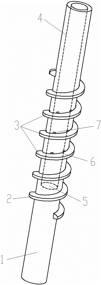
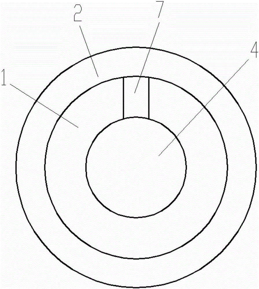
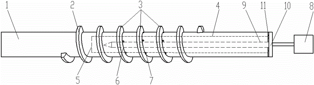
[0018] Attached below Figure 1-3 An embodiment of the present invention is described.

[0019] Worm with built-in lubrication structure, such as figure 1 As shown, the worm body 1 is included. The outer surface of the worm body 1 is provided with worm spiral teeth 2. During the working process of the worm, only a part of the worm spiral teeth 2 meshes with the worm wheel, and the worm spiral teeth 2 mesh with the worm wheel. It is set as the worm meshing tooth part 3, and the use rate of the worm meshing tooth part 3 is high, so the lubrication system is also high. In this solution, a gear pump 8 is added to the worm gear box, and the lubrication structure of the worm is changed to achieve a better lubrication effect. That is, under the premise of ensuring the transmission strength of the worm, a blind hole 4 is drilled at one end of the worm body 1 to ensure that the worm meshing teeth 3 of the worm meshing with the worm wheel are effectively lubricated, so that the bottom of ...


PUM


Abstract

Provided is a worm with a built-in lubricating structure. The worm comprises a worm body. Worm helical teeth is arranged on the outer surface of the worm body, and a part, where the worm helical teeth meshes with a worm gear in a matched mode, on the worm helical teeth is a worm meshing teeth part. One end part of the worm body is provided with a blind hole, the worm meshing teeth part is evenly provided with a plurality of oil spit holes upward along a worm spiral line shaft, and the oil spit holes are communicated with an inner cavity of the blind hole. According to the worm with the built-in lubricating structure, the structure of the worm is improved, and the flow path of lubricating oil is changed, so that the lubricating oil directly is sprayed to the meshing part of the worm and the worm gear through the blind hole and the oil spit holes, and the flow speed of the lubricating oil is accelerated, therefore, heat dissipation is expedited, and the reliability of a lubricating system is improved.

Description

Technical field [0001] The invention belongs to the technical field of worms, and specifically relates to a worm with a built-in lubricating structure. Background technique [0002] Worm drive is a transmission structure that transmits motion and power between two shafts that are staggered in space. The angle of the staggered axis can be any value, and the commonly used one is 90 degrees. This kind of transmission has the following characteristics, so it is quite useful widely. 1. When a single-head worm is used and is equivalent to a single thread, the worm wheel only rotates one pitch for each revolution of the worm, so a large transmission ratio can be achieved. In power transmission, the general transmission ratio i=5~80. In the transmission of indexing mechanism or manual mechanism, the transmission ratio can reach 300. If only movement is transmitted, the transmission ratio can reach 1000. Due to the large transmission ratio, the number of parts is reduced by Because the ...

Claims


Application Information

Patent Timeline
Patent Type & Authority Applications(China)
IPC IPC(8): F16H55/22F16H57/04
CPCF16H55/22F16H57/0427F16H57/0498
Inventor 梁磊王娟平魏宗平
Owner BAOJI UNIV OF ARTS & SCI
Why Eureka
Try Eureka