Embedded piezoelectric drive micro oil spraying lubrication device

A technology of piezoelectric drive and oil injection lubrication, which is applied in the direction of dosing device, engine lubrication, distribution device, etc., can solve the problem that micro-redundant supplementary oil supply lubrication is difficult to realize, and achieve light weight, small volume and simple structure Effect

Inactive Publication Date: 2017-02-22
HARBIN INST OF TECH
View PDF4 Cites 9 Cited by
  • Summary
  • Abstract
  • Description
  • Claims
  • Application Information

AI Technical Summary

Problems solved by technology

[0005] In order to solve the problem that the micro-redundant supplementary oil supply lubrication of the existing space liquid lubrication system is difficult to realize, the present invention further proposes an embedded piezoelectric-driven micro-quantity oil injection lubrication device

Method used


Image

  • Embedded piezoelectric drive micro oil spraying lubrication device
  • Embedded piezoelectric drive micro oil spraying lubrication device
  • Embedded piezoelectric drive micro oil spraying lubrication device

Examples


specific Embodiment approach 1

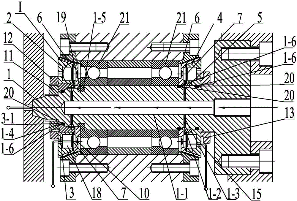
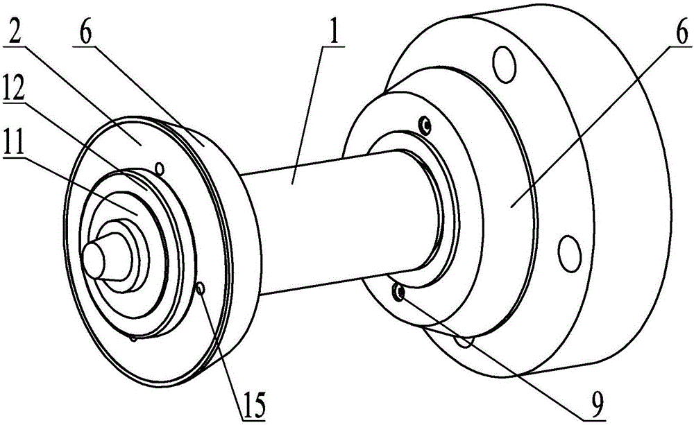
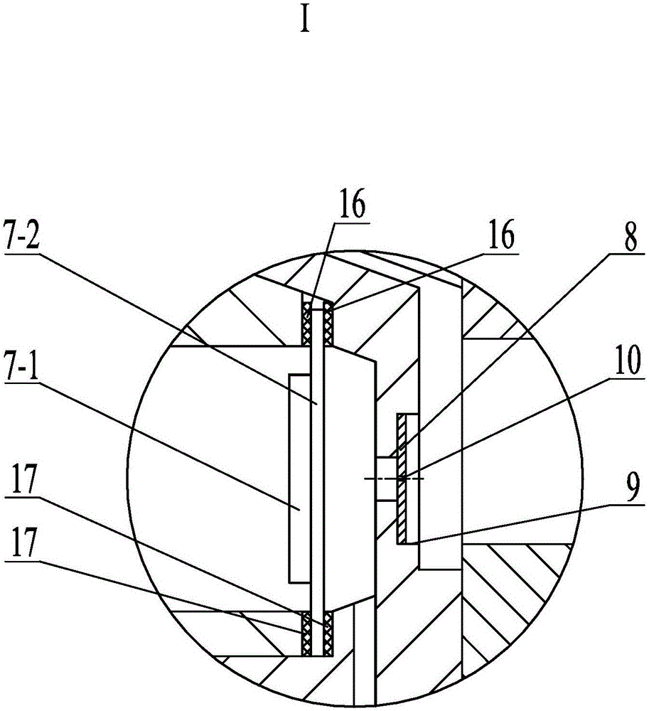
[0021] Specific implementation mode one: combine Figure 1 to Figure 7 To illustrate, an embedded piezoelectric-driven micro-spray lubrication device described in this embodiment includes a mandrel 1, a front micro-spray cover 2, a front guide ring 3, a rear micro-spray cover 4, a rear guide ring 5, two The micro-spray chamber body 6, two piezoelectric vibrators 7 and four metal discs 8, the central part of the mandrel 1 is provided with a hollow channel 1-1 along the axial direction, the shape of the micro-spray chamber body 6 is ring-shaped, and the mandrel The front and rear ends of 1 are respectively equipped with a micro-spray cavity body 6, the shape of the cross-section of the micro-spray cavity body 6 is conical, and the small end faces of the two micro-spray cavity bodies 6 are oppositely arranged, and each micro-spray cavity body 6 Two circular grooves 9 are respectively arranged symmetrically along the radial direction on the small end surface, and a metal disc 8 is...

specific Embodiment approach 2

[0025] Specific implementation mode two: combination Figure 1 to Figure 2 Explanation, the large end faces of the front micro-spray cover 2 and the rear micro-spray cover 4 in this embodiment are respectively provided with through holes 15, and the positive lead wire of the driving power is connected to the top of the annular piezoelectric ceramic sheet 7-1 in the piezoelectric vibrator 7. surface, and drawn out from the through hole 15, the negative electrode lead is connected to the mandrel 1. Other compositions and connection methods are the same as those in Embodiment 1.

[0026] When the piezoelectric-driven micro-spray lubrication device of this embodiment is applied, the positive lead of the piezoelectric vibrator 7 is connected to the upper surface of the annular piezoelectric ceramic 7-1, drawn out from the through hole 15, and connected to the signal generating end of the driving power supply. The negative lead wire can be directly connected to the metal outer wall...

specific Embodiment approach 3

[0027] Specific implementation mode three: combination Figure 1 to Figure 3 and Figure 6 To illustrate, the annular piezoelectric ceramic sheet 7 - 1 in the piezoelectric vibrator 7 in this embodiment is polarized in the thickness direction. Other compositions and connection modes are the same as those in Embodiment 1 or 2.

[0028] In such a design, the annular piezoelectric ceramic sheet 7-1 adopts the method of polarization in the thickness direction, and a voltage pulse excitation of a certain frequency and waveform is applied to its upper and lower surfaces to increase the bending deformation of the piezoelectric vibrator 7, thereby increasing the volume of the liquid cavity. As the variation increases, the resulting acoustic pressure wave increases.


PUM


Abstract

The invention discloses an embedded piezoelectric drive micro oil spraying lubrication device, relates to the technical field of space lubrication and piezoelectric micro spraying, in particular to the embedded piezoelectric drive micro oil spraying lubrication device, and aims to solve the problem of difficult realization of micro redundancy oil supply replenishing lubrication in a traditional space liquid lubrication system. The embedded piezoelectric drive micro oil spraying lubrication device comprises a mandrel, a front micro spraying cover, a front guide ring, a back micro spraying cover, a back guide ring, two micro spraying cavities, two piezoelectric vibrators and four metal discs; two micro spraying cavities respectively sleeve the front and back ends of the mandrel; two circular grooves are symmetrically formed in the small end surface of each micro spraying cavity in the radial direction; one metal disc is embedded in each circular groove; micro holes are formed in the centers of the metal discs; the piezoelectric vibrators are respectively arranged between the front micro spraying cover and the micro spraying cavity at the front end as well as between the back micro spraying cover and the micro spraying cavity at the back end; and cavities are formed between the front micro spraying cover and the piezoelectric vibrator at the front end as well as between the back micro spraying cover and the piezoelectric vibrator at the back end. The embedded piezoelectric drive micro oil spraying lubrication device is used for space lubrication.

Description

technical field [0001] The invention relates to the technical fields of space lubrication and piezoelectric micro-spraying, in particular to an embedded piezoelectric-driven micro-spraying lubrication device. Background technique [0002] Over the years, research in the field of space lubrication has always been a hot spot in the world. Solid lubrication has the advantages of stable lubrication performance, no volatilization and crawling phenomenon, and wide operating temperature range. It has been one of the main lubrication methods for spacecraft and space stations from the initial stage of space lubrication to the present stage. However, compared with liquid lubrication, solid lubrication has disadvantages such as large frictional resistance, poor heat transfer performance, and inability to self-repair. Liquid lubrication is an effective lubrication method for bearings of high-speed, variable load, heavy load and impact load space mechanical parts. [0003] After decade...

Claims


Application Information

Patent Timeline
Patent Type & Authority Applications(China)
IPC IPC(8): F16N25/00F16N27/00
CPCF16N25/00F16N27/00
Inventor 刘军考李锴杨锐陈维山
Owner HARBIN INST OF TECH
Why Eureka
Try Eureka