Bridge dynamic deflection detection method and device based on microwave interference

A microwave interference and bridge technology, applied in the direction of measuring devices, elastic testing, radio wave measurement systems, etc., can solve the problems of low precision, small detection range, short detection distance, etc., and achieve the effect of improving detection accuracy

Inactive Publication Date: 2017-02-22
BEIJING UNIV OF CIVIL ENG & ARCHITECTURE
View PDF5 Cites 4 Cited by
  • Summary
  • Abstract
  • Description
  • Claims
  • Application Information

AI Technical Summary

Problems solved by technology

[0004] Laser is a high-precision technology for detecting displacement changes, with an accuracy of up to 0.1mm, but its equipment is expensive and cannot obtain displacement changes perpendicular to the laser beam
GPS is suitable for dynamic displacement detection of large flexible structures (such as suspension bridges), but because its error is almost the same order of magnitude as the displacement value, it is not suitable for dynamic deformation detection of reinforced concrete structures with small displacement changes, and sampling The frequency is generally lower than 20Hz, and random noise and multipath effects increase the difficulty of data analysis
Visual inspection is another effective non-contact inspection method, which is mainly composed of high-speed cameras, synchronous controllers, high-speed acquisition cards and artificial target points. Although its relative accuracy can reach 1:10000, massive data processing and control network The complexity of layout greatly reduces the efficiency
In short, the traditional dynamic deflection detection technology has a small detection range, a short detection distance, low precision, and is greatly affected by the environment.

Method used


Image

  • Bridge dynamic deflection detection method and device based on microwave interference
  • Bridge dynamic deflection detection method and device based on microwave interference
  • Bridge dynamic deflection detection method and device based on microwave interference

Examples


Embodiment Construction

[0040] In order to make the purpose, technical solutions and advantages of the embodiments of the present invention clearer, the technical solutions in the embodiments of the present invention will be clearly and completely described below in conjunction with the drawings in the embodiments of the present invention. Obviously, the described embodiments It is a part of embodiments of the present invention, but not all embodiments. Based on the embodiments of the present invention, all other embodiments obtained by persons of ordinary skill in the art without making creative efforts belong to the protection scope of the present invention.

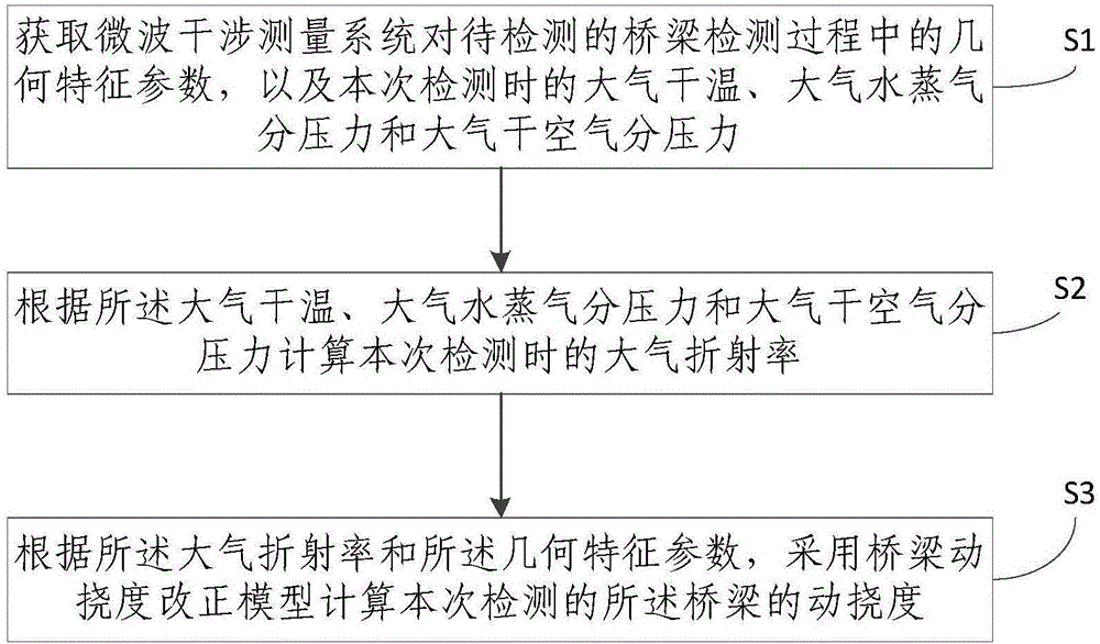
[0041] figure 1 It is a schematic flow chart of the method for detecting bridge dynamic deflection based on microwave interference provided in this embodiment, see figure 1 , the method includes:

[0042] S1: Obtain the geometric characteristic parameters of the bridge to be detected by the microwave interference detection system, as well a...


PUM


Abstract

The invention discloses a bridge dynamic deflection detection method and device based on microwave interference. The method includes the steps: S1 acquiring geometrical characteristic parameters of a microwave interference detection system for a bridge to be detected in the detection process, and acquiring atmospheric dry temperature, atmospheric steam partial pressure and atmospheric dry air partial pressure in detection; S2 calculating an atmospheric refraction index in detection according to the atmospheric dry temperature, the atmospheric steam partial pressure and the atmospheric dry air partial pressure; S3 calculating dynamic deflection of the bridge in detection by a bridge dynamic deflection correction model according to the atmospheric refraction index and the geometrical characteristic parameters. According to the method, the influence of the atmospheric dry temperature, the atmospheric steam partial pressure and the atmospheric dry air partial pressure on the microwave propagation process is taken into consideration, the influence of environmental factors such as temperature, humidity and atmospheric pressure on ground microwave interference detection precision due to season and time difference is avoided, and dynamic deflection detection precision of the bridge is improved.

Description

technical field [0001] The invention belongs to the technical field of bridge detection, and in particular relates to a method and device for detecting bridge dynamic deflection based on microwave interference. Background technique [0002] With the development of high-speed railways, the operating mileage of my country's high-speed railways has reached 20,000 kilometers. Among them, bridges account for an average of 54% of the route. During the operation of railway bridges, various degrees of damage and destruction will be caused due to various reasons. In order to ensure the safe operation of existing railway bridges and prolong their service life as much as possible, a high-frequency, high-precision technical means is needed to detect the deflection of the beam body when it is overloaded, and then analyze its health status and safety. Evaluate. [0003] At present, the technologies used to detect the dynamic deflection of railway bridges are divided into contact method...

Claims


Application Information

Patent Timeline
Patent Type & Authority Applications(China)
IPC IPC(8): G01M5/00G01S13/88
CPCG01M5/0008G01S13/88
Inventor 刘祥磊卢钊吕京国周命端
Owner BEIJING UNIV OF CIVIL ENG & ARCHITECTURE
Why Eureka
Try Eureka