Microprobe scattering type terahertz waveband dielectric constant detecting device
A dielectric constant and detection device technology, applied in the field of terahertz technology applications, can solve the problems of inability to detect the dielectric constant of micro-nano-scale samples, detection accuracy, deficiency, and upper limit of resolution, and achieve high integration, Simplifies complex work and highly operable effects
- Summary
- Abstract
- Description
- Claims
- Application Information
AI Technical Summary
Problems solved by technology
Method used
Image
Examples
Embodiment 1
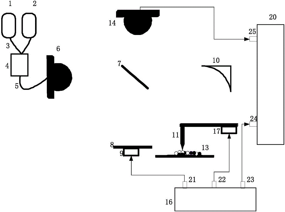
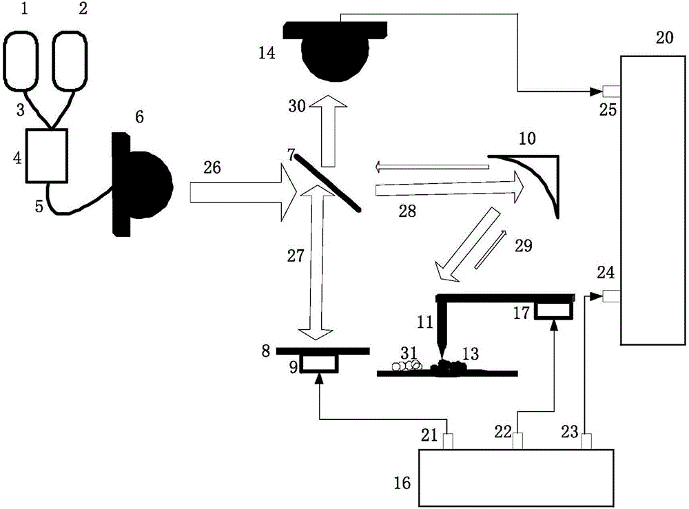
[0070] A microprobe scattering type dielectric constant detection device in the terahertz band, comprising a first infrared laser 1, a second infrared laser 2, a front-end polarization-maintaining optical fiber 3, a coupling beam splitter 4, a rear-end polarization-maintaining optical fiber 5, and a THz Wave transmitting antenna 6, THz wave splitter 7, THz wave reflector 8, first actuating ceramic 9, micro-nano probe 11, second actuating ceramic 17, parabolic mirror 10, THz wave power detector 14, function The generator 16 and the lock-in amplifier 20 are composed; the THz wave reflector 8 and the first actuating ceramic 9 are bonded together by synthetic resin glue; the micro-nano probe 11 and the second actuating ceramic 17 are mechanically clamped by micro-bolts Connection; the focal point of the THz wave transmitting antenna 6, the center of the THz wave splitter 7 and the horizontal axis of the parabolic mirror 10 are on the same straight line; the center of the THz wave r...
Embodiment 2
[0083] A microprobe scattering type dielectric constant detection device in the terahertz band, comprising a first infrared laser 1, a second infrared laser 2, a front-end polarization-maintaining optical fiber 3, a coupling beam splitter 4, a rear-end polarization-maintaining optical fiber 5, and a THz Wave transmitting antenna 6, THz wave splitter 7, THz wave reflector 8, first actuating ceramic 9, micro-nano probe 11, second actuating ceramic 17, parabolic mirror 10, THz wave power detector 14, function The generator 16 and the lock-in amplifier 20 are composed; the THz wave reflector 8 and the first actuating ceramic 9 are bonded together by synthetic resin glue; the micro-nano probe 11 and the second actuating ceramic 17 are mechanically clamped by micro-bolts Connection; the focal point of the THz wave transmitting antenna 6, the center of the THz wave splitter 7 and the horizontal axis of the parabolic mirror 10 are on the same straight line; the center of the THz wave r...
Embodiment 3
[0085] A microprobe scattering type terahertz band dielectric constant detection device is characterized in that the calculation method of the dielectric constant (ε) of the substance to be measured is:
[0086]
[0087]
[0088] In the formula, k is the characteristic parameter value of the system; I x and I y Two orthogonal component signals at 2Ω-M and 2Ω-2M frequencies measured on a terahertz-band dielectric constant detection device for a standard sample with known dielectric function; α is the terahertz-band dielectric constant detection device The dielectric constant of the tip coating of the micro-nano probe 11 is a known value in the test; ε 0 is the dielectric constant of the standard sample, also known value; Ω is the vibration frequency of the micro-nano probe; r is the radius of curvature of the tip of the micro-nano probe 11; A is the vibration amplitude of the micro-nano probe 11 ;I' x and I' y are two orthogonal component signals of the sample to be t...
PUM
 Abstract
Description
Claims
Application Information
 - R&D
- Intellectual Property
- Life Sciences
- Materials
- Tech Scout
- Unparalleled Data Quality
- Higher Quality Content
- 60% Fewer Hallucinations
Browse by: Latest US Patents, China's latest patents, Technical Efficacy Thesaurus, Application Domain, Technology Topic, Popular Technical Reports.
© 2025 PatSnap. All rights reserved.Legal|Privacy policy|Modern Slavery Act Transparency Statement|Sitemap|About US| Contact US: help@patsnap.com


