Multi-business digital light distribution system and multi-business capacity scheduling method

A distributed system and digital optical technology, which is applied to the selection device, electrical components, selection device, etc. Effects of microwave transmission, improved reliability, and fewer types of equipment

Pending Publication Date: 2017-02-22
GUANGZHOU EYECOM TELECOMM
View PDF2 Cites 17 Cited by
  • Summary
  • Abstract
  • Description
  • Claims
  • Application Information

AI Technical Summary

Problems solved by technology

According to its instruction manual, from the perspective of indoor coverage, the disadvantages are as follows: 1. The entire coverage network adopts a three-layer structure, the product application is complex, and it takes up a lot of space, especially not suitable for high-power RRU coverage; 2. MAU does not support wireless Access signal, limited application environment 3. Does not support private network system; 4. Does not support TDD signal coverage, limited application environment

Method used


Image

  • Multi-business digital light distribution system and multi-business capacity scheduling method
  • Multi-business digital light distribution system and multi-business capacity scheduling method
  • Multi-business digital light distribution system and multi-business capacity scheduling method

Examples


Embodiment Construction

[0034] In order to make the purpose of the invention, technical solution and beneficial technical effects of the present invention clearer, the present invention will be further described in detail below in conjunction with the accompanying drawings and specific implementation methods. It should be understood that the specific implementations described in this specification are only for explaining the present invention, not for limiting the present invention.

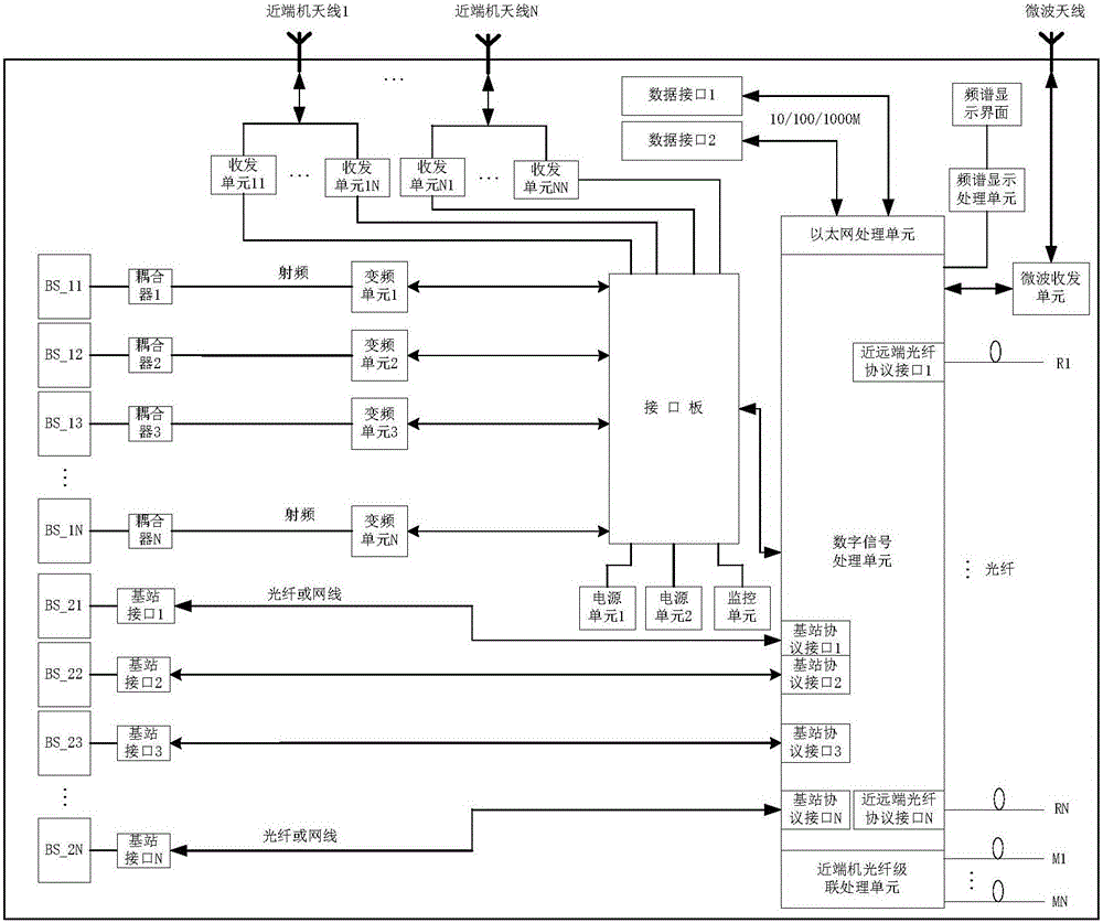
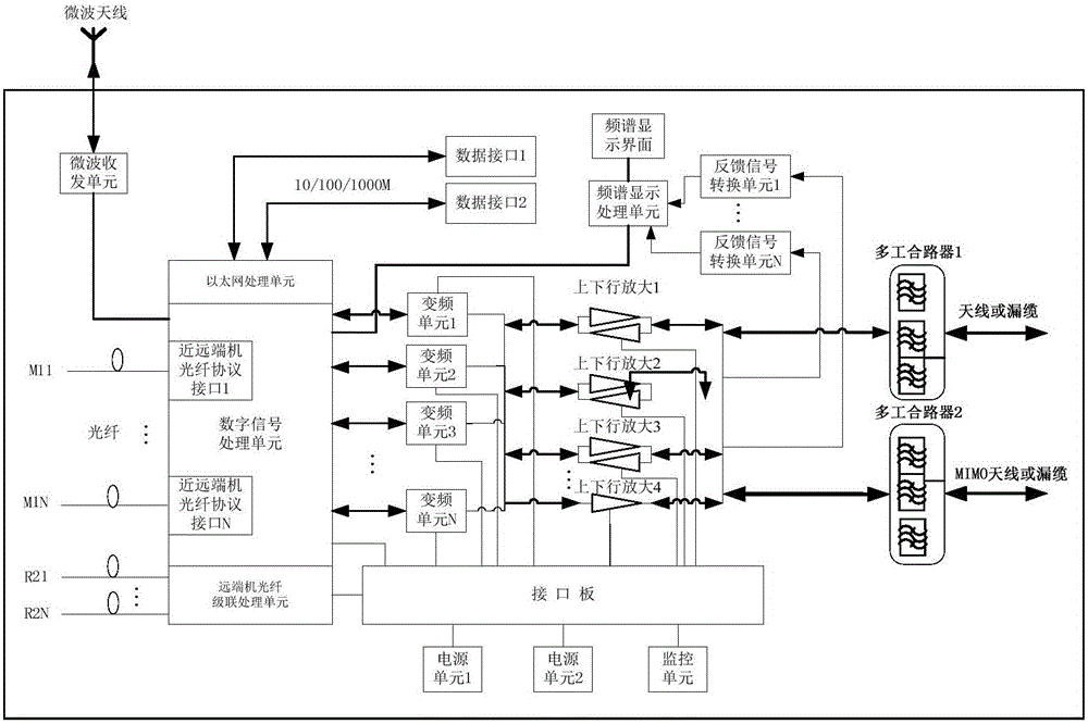
[0035] see Figures 1 to 11 , the near-end unit of the multi-service digital optical distribution system of the present invention includes: near-end unit antenna 1...N, near-end unit microwave antenna, transceiver unit 11...1N, transceiver unit N1...NN, coupler 1...N, frequency conversion unit 1 …N, interface board, power supply unit 1, power supply unit 2, monitoring unit, digital signal processing unit, Ethernet processing unit, data interface 1, data interface 2, microwave transceiver unit, near-end optical fiber cas...


PUM


Abstract

The invention discloses a multi-business digital light distribution system. The system comprises a near-end machine and a far-end machine, wherein in the near-end machine, a downlink signal entering the near-end machine and is processed, a signal is from a data interface and passes through an Ethernet processing unit, base-band CPRI framing for the downlink signal after processing and the signal from the data interface is carried out, the signals are then converted through a digital light module into light signals or are converted through a fiber or a microwave transceiving unit into microwave signals which are transmitted to the far-end machine; in the far-end machine, the light signals from the near-end machine are converted through the digital light module in the far-end machine into digital signals, the digital signals after CPRI deframing are converted into a base-band signal and an Ethernet signal, the Ethernet signal passes through an Ethernet processing unit and is transmitted through the data interface to other data terminal; the microwave signals from the near-end machine are converted through a microwave antenna in the far-end machine and the microwave reception unit into intermediate frequency signals which enter the digital signal processing unit and are converted into base-band signals after analog-digital conversion, the two types of base-band signals are converted into intermediate frequency signals through the digital signal processing unit, the intermediate frequency signals are then converted into radiofrequency signals through a frequency conversion unit, and the radiofrequency signals after downlink amplification enter a multiplex combiner and are emitted through the antenna.

Description

technical field [0001] The invention relates to mobile communication and private network communication technology, more specifically, to a multi-service digital optical distribution system and a multi-service capacity scheduling method. Background technique [0002] The rapid development of mobile communication technology has driven the explosive growth of mobile Internet and broadband data services, which has brought great challenges to traditional network coverage and optimization. For example, if the existing single- or dual-band optical fiber repeater equipment is used, multiple devices have to be used in multi-band and multi-standard coverage cells, resulting in increased costs and increased installation complexity. If the coverage method of BBU (Baseband Unit, baseband unit) + RRU (Radio Remote Unit, remote unit) is adopted, since RRU (Radio Remote Unit, remote unit) can basically only support single frequency, it cannot satisfy multi-frequency , Multi-mode requiremen...

Claims


Application Information

Patent Timeline
Patent Type & Authority Applications(China)
IPC IPC(8): H04Q11/00
CPCH04Q11/0067
Inventor 介利军方耀关淇陈志聪
Owner GUANGZHOU EYECOM TELECOMM
Why Eureka
Try Eureka