Method for manufacturing nickel-silicon alloy

A manufacturing method, silicon alloy technology, applied in the preparation of organic compounds, chemical instruments and methods, preparation of hydroxyl compounds, etc., can solve problems such as the inability to restore catalyst functions, and achieve the effect of ensuring safety and excellent environment

Active Publication Date: 2017-02-22
JNC CORP
View PDF7 Cites 0 Cited by
  • Summary
  • Abstract
  • Description
  • Claims
  • Application Information

AI Technical Summary

Problems solved by technology

[0017] In addition, the method described in Patent Document 2 utilizes a phenomenon unique to hydrolysis, and has the problem that even if the catalyst used in the double bond hydrogenation is reused by the same method, the catalyst function cannot be recovered.

Method used


Image

  • Method for manufacturing nickel-silicon alloy
  • Method for manufacturing nickel-silicon alloy
  • Method for manufacturing nickel-silicon alloy

Examples


preparation example Construction

[0102] (Preparation of Sponge Nickel as Hydrogenation Catalyst)

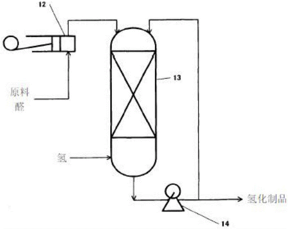
[0103] The production method of sponge nickel, which is the maximum application of the nickel-silicon alloy produced in the present invention, is described in a large number of documents (for example, non-patent document 1, non-patent document 2). In general, a nickel-silicon alloy is developed in an alkaline aqueous solution and washed with water to obtain sponge nickel that can be used as a hydrogenation catalyst.

[0104] (Preparation of Sponge Nickel Catalyst: Expand)

[0105] An example of a method for preparing a sponge nickel catalyst is as follows.

[0106] The method of adjusting sponge nickel for fixed-bed hydrogenation device with a diameter of 25mm to 6mm is to develop nickel-silicon alloy in 48% sodium hydroxide solution at 85°C for 2 hours and 45 minutes, cool to room temperature, and wash with water for more than 8 hours. Obtain nickel sponge for hydrogenation. The nickel content of the nickel ...

Embodiment 1

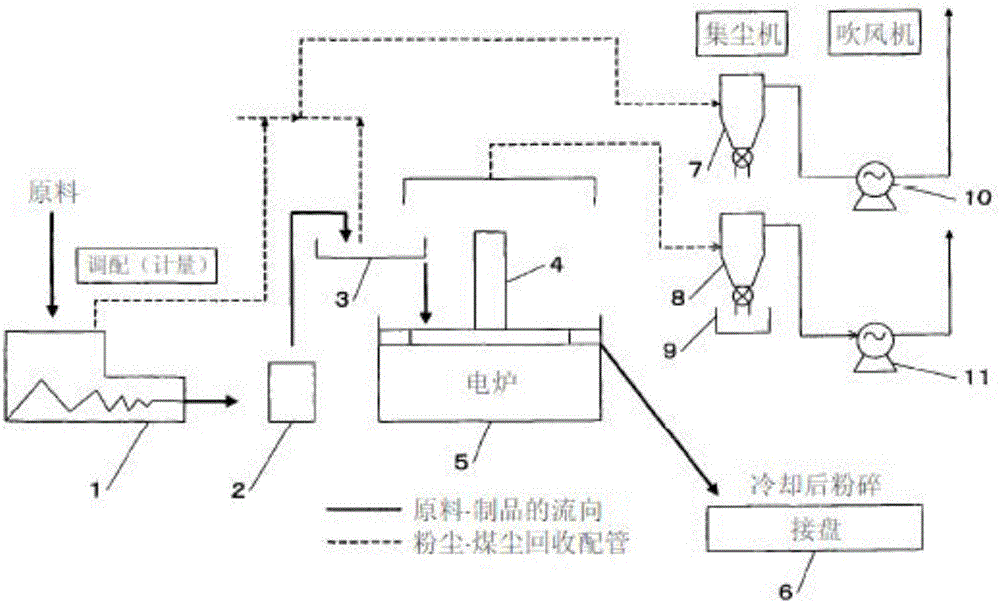
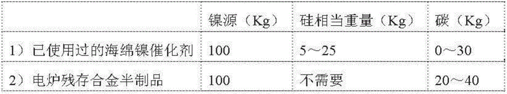
[0123] As the nickel source of the raw material, relative to the used sponge nickel catalyst 100kg (nickel 62.7% by weight, silicon 34.4% by weight, iron 2.9% by weight), use an electric furnace residual alloy semi-finished product 5kg (nickel 35.8% by weight, silicon 61.6% by weight) , iron 2.6% by weight), new nickel 5.65kg, silicon source uses silica 41.1kg, carbon source uses charcoal 26.9kg, utilizes figure 1 Nickel-silicon alloys are produced by the method described in the nickel-silicon alloy production flow diagram shown. If the remaining alloy semi-products in the electric furnace are removed, a nickel-silicon alloy product with a specific gravity of 4.89, nickel 54.2 wt%, silicon 43.4 wt%, and iron 2.3 wt% is obtained with a yield of 99%.

Embodiment 2

[0125] As a nickel source as a raw material, 100 kg of a used sponge nickel catalyst (62.7% by weight of nickel, 34.4% by weight of silicon, and 2.9% by weight of iron) was used. In contrast, 30 kg of silica was used as a source of silicon, and 20 kg of charcoal was used as a carbon source. figure 1 Nickel-silicon alloys are produced by the method described in the nickel-silicon alloy production flow diagram shown. If the remaining alloy semi-products in the electric furnace are removed, a nickel-silicon alloy product with a specific gravity of 4.9, nickel 55.0 wt%, silicon 42.5 wt%, and iron 2.5 wt% is obtained with a yield of 99%.


PUM

PropertyMeasurementUnit
Diameteraaaaaaaaaa

Abstract

The present invention provides a method for manufacturing a nickel-silicon alloy by using a used nickel-silicon sponge catalyst as a part of the source material. The invention is mainly comprised of supplying to an electric furnace a silicon source, a carbon source, and a nickel source comprising a used sponge nickel catalyst, and performing a heating reaction for 4-30 hours at a furnace temperature of 1,200-1,500 DEG C. A mixture of new nickel, used sponge nickel catalyst, and semi-finished nickel-silicon alloy residue from an electric furnace can be used as the nickel source; a substance obtained by mixing silicon metal with silica stone can be used as the silicon source; and commercially available charcoal and / or sumi charcoal can be used as the carbon source. The temperature in the electric furnace is most preferably 1,230-1,270 DEG C.

Description

technical field [0001] The present invention relates to a method for producing a nickel-silicon alloy using a spent catalyst of a sponge nickel catalyst as a hydrogenation catalyst as a raw material. Background technique [0002] Sponge nickel hydrogenation catalyst is a catalyst invented by Muray Raney (Muray Raney), usually known by the name of Raney Nickel (Raney Nickel) as a trade name, as described in US Patent No. 1,628,190 specification, It is a metal catalyst obtained by preparing an alloy of a metal having a catalytic action and a metal that does not have a catalytic action, and partially elution-removing the metal that does not have a catalytic action with an alkaline aqueous solution (this operation is called "development") . [0003] Muray Raney also studied ternary systems in which silicon was added in addition to the combination of nickel and aluminum. If a mixture of silicon and aluminum is used, alloy production becomes complicated because the properties of...

Claims


Application Information

Patent Timeline
IPC IPC(8): C22C1/02B01J25/02B01J25/04B01J38/02C22B7/00C22C1/08C22C19/03C07C29/141C07C31/125
CPCB01J25/02B01J25/04B01J38/02C07C29/141C07C31/125C22B7/00C22C1/02C22C1/08C22C19/03Y02P10/20Y02P20/584
Inventor 児岛健志河村栄
Owner JNC CORP
Why Eureka
Try Eureka