
Multistage compressor system with hydrodynamic fluid coupling

A technology for hydraulic couplers and compressors, applied in mechanical equipment, machines/engines, liquid fuel engines, etc., can solve problems such as impossible, and achieve the effect of improved efficiency and high efficiency

Inactive Publication Date: 2017-02-22
哈拉尔德文策尔
View PDF12 Cites 0 Cited by
  • Summary
  • Abstract
  • Description
  • Claims
  • Application Information

AI Technical Summary

Problems solved by technology

[0020] The combined arrangement of turbo compressor and screw compressor is disclosed in the publications US-PS 36 40 646 and FR-PS 13 97 614, but these solutions also have disadvantages, because here the turbo compressor and screw compressor The compressors are operated on one shaft at the same rotational speed, whereby optimal operation at good efficiency is also not possible for the volume and pressure ranges involved in the invention as in multistage compressors of the same type

Method used


Image

  • Multistage compressor system with hydrodynamic fluid coupling
  • Multistage compressor system with hydrodynamic fluid coupling

Examples


Embodiment Construction

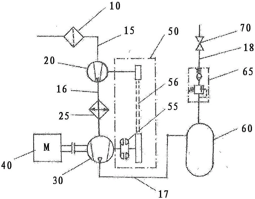
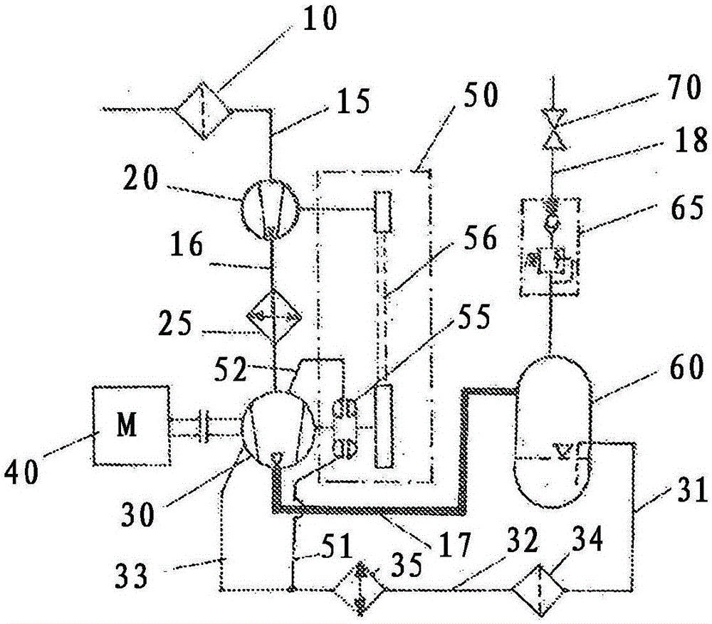
[0069] in accordance with figure 1 In the compressor installation, the suction air is cleaned by an air filter 10 and then fed to a pre-compressor 20 via a connecting line 15 . The precompressed suction air is fed to an intercooler 25 via a further connecting line 16 and cooled as best as possible. The cooled and precompressed air is then delivered to the main compressor 30 .

[0070] The main compressor can in principle be any type of compressor, also a multi-stage compressor, with or without intercooling between the individual compressor stages of the main compressor.

[0071] The main compressor 30 is driven by a drive motor 40 . The drive motor 40 can also be of any structural form that can be used to drive the compressor. This can be, for example, an electric motor, a combustion engine or any type of turbine.

[0072] In the main compressor 30 the compressed air is compressed to the desired operating pressure and delivered via the connecting line 17 to the pressure ve...


PUM


Abstract

A compressor system for producing a compressed gas, more particularly air, comprising at least one main compressor (30) which is supplied with pre-compressed gas with the aid of a pre-compressor (20), wherein the at least one main compressor (30) and also the at least one pre-compressor (20) are driven by a shared drive motor (40) or by separate drives, and at least one pre-compressor (20) is linked to a fluid coupling (55) that changes the drive speed of the pre-compressor (20).

Description

technical field [0001] The invention relates to a compressor device for generating compressed gas according to the preamble of claim 1 . Background technique [0002] Compressor installations used in industry and production trade consume large amounts of electrical energy, or in mobile installations due to the use of internal combustion engines consume limited natural resources based on petroleum or renewable energy carriers such as biofuels. Due to rising energy costs and environmental pollution due to energy consumption, efforts are increasing to reduce energy consumption and thereby simultaneously reduce costs and consumption of natural resources. [0003] Among the compressor equipment used today, the compressor equipment for generating compressed air is the most extensive equipment. However, plants for generating various types of process gases or for conveying gases over relatively large distances are also designed as compressor plants, the drive power of which reaches...

Claims


Application Information

Patent Timeline
Patent Type & Authority Applications(China)
IPC IPC(8): F04C23/00F04C29/00F04D25/04F04D25/16F04D27/02
CPCF04C23/006F04C29/005F04D25/04F04D25/16F04D27/0261F04D17/10F04C18/16F04C23/005F04C29/0085F04C2270/0525F04D17/12F04D25/022Y02B30/70F04D13/06F04D13/02F04D13/12F04D15/0072F04B35/002F04B41/06
Inventor 哈拉尔德·文策尔
Owner 哈拉尔德文策尔
Learn More