Supercharge Your Innovation With Domain-Expert AI Agents!

Method for operating a chiller

A technology of coolers and condensers, which is applied to evaporators/condensers, refrigerators, refrigeration components, etc., and can solve problems such as short duration

Active Publication Date: 2017-02-22
JOHNSON CONTROLS TYCO IP HLDG LLP
View PDF11 Cites 0 Cited by
  • Summary
  • Abstract
  • Description
  • Claims
  • Application Information

AI Technical Summary

Problems solved by technology

[0005] Unfortunately, such environmental conditions occur relatively rarely in many parts of the world, or may be of short duration

Method used


Image

  • Method for operating a chiller
  • Method for operating a chiller
  • Method for operating a chiller

Examples


Embodiment Construction

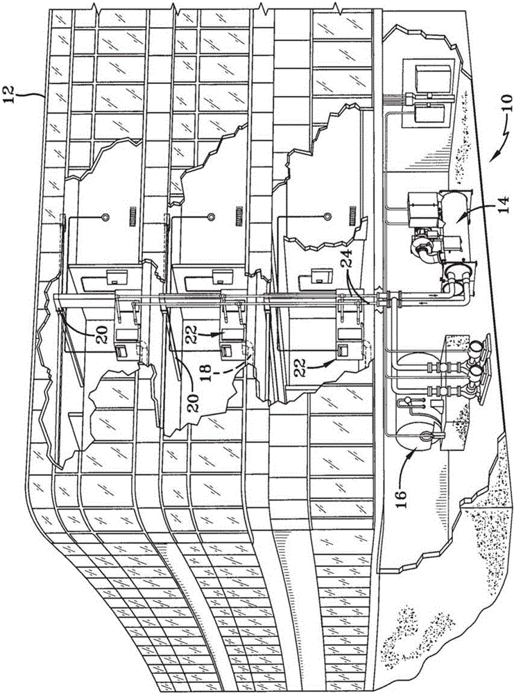
[0020] figure 1 An exemplary environment is shown for a heating, ventilation, and air conditioning (HVAC) system 10 that includes a cooling liquid system for a typical commercial setting. System 10 may include a vapor compression system 14 capable of providing a cooling liquid that may be used to cool building 12 . System 10 may include a boiler 16 to provide heated liquid that may be used to heat building 12 and an air distribution system to circulate air through building 12 . The air distribution system may also include air return duct 18 , air supply duct 20 , and air handler 22 . Air handler 22 may include a heat exchanger connected to boiler 16 and vapor compression system 14 by conduit 24 . The heat exchanger in air handler 22 may receive heated liquid from boiler 16 or cooled liquid from vapor compression system 14 depending on the mode of operation of system 10 . System 10 is shown with separate air handlers on each floor of building 12, but it is understood that th...


PUM


Abstract

The invention provides method of operating a chiller having a closed refrigerant loop including a compressor, a condenser and an evaporator. The refrigerant used in the loop defining a pressure-enthalpy curve representative of different phases (vapor, liquid and vapor, and liquid) of the refrigerant at different combinations of pressure and enthalpy. The loop defines a process cycle (compression, condensation, expansion, and evaporation) of the refrigerant during operation of the loop relative to the pressure-enthalpy curve of the refrigerant. The method includes continuously operating the compressor when a segment of the process cycle corresponds to the refrigerant being in the liquid phase.

Description

Background technique [0001] This application relates generally to refrigeration, air conditioning and cooling liquid systems. The present application relates more particularly to methods of operating refrigeration, air conditioning and coolant systems. [0002] It has been recognized that under certain environmental conditions and reduced system cooling requirements, coolant systems using centrifugal compressors can be Runs at a fraction of the cost. The 2008 ASHRAE Handbook - HVAC Systems and Equipment (page 42.12) states the following: [0003] Cooling of a compressor without running a centrifugal liquid cooler is called free cooling. Some chillers are capable of operating as thermosiphons when a supply of condensate is available at a temperature lower than the desired cooling water temperature. The low temperature condensate condenses the refrigerant which is either drained by gravity or pumped to the evaporator. The higher temperature cooling water evaporates the refr...

Claims


Application Information

Patent Timeline
Patent Type & Authority Applications(China)
IPC IPC(8): F25B1/00F25B49/02
CPCF25B1/00F25B49/022F25B49/025F25B2600/0253F25B2700/21173F25B2700/21161F25B2339/047F25B1/02F25B1/04F25B25/005F25B2313/003F25B2313/004Y02B30/70F25B13/00
Inventor 杰布·W·施雷柏
Owner JOHNSON CONTROLS TYCO IP HLDG LLP
Features
  • R&D
  • Intellectual Property
  • Life Sciences
  • Materials
  • Tech Scout
  • Unparalleled Data Quality
  • Higher Quality Content
  • 60% Fewer Hallucinations
Learn More