Heat pipe cooling system and power equipment

A heat dissipation system and power equipment technology, applied in lighting and heating equipment, electrical equipment structural parts, electrical components, etc., can solve problems such as high cost, quick connector leakage, system short circuit, etc., and achieve small driving force, stability and reliability , high heat transfer efficiency

Active Publication Date: 2017-02-22
XFUSION DIGITAL TECH CO LTD
View PDF22 Cites 11 Cited by
  • Summary
  • Abstract
  • Description
  • Claims
  • Application Information

AI Technical Summary

Problems solved by technology

Since the working fluid is driven by a pump and the pressure is high, when the board is connected to the system pipeline, there is a risk of leakage at the quick connector, and the liquid dripping onto the board will cause a short circuit in the system
Moreover, the pump is a moving part, the reliability requirements are very high, and backup is required, and the cost is very high

Method used


Image

  • Heat pipe cooling system and power equipment
  • Heat pipe cooling system and power equipment
  • Heat pipe cooling system and power equipment

Examples


Embodiment Construction

[0030] The technical solutions in the embodiments of the present invention will be clearly described below with reference to the drawings in the embodiments of the present invention.

[0031] The present invention provides a heat pipe heat dissipation system and power equipment including the heat pipe heat dissipation system. The power equipment may be communication equipment. The power equipment includes an electronic module that generates heat during operation. The heat pipe heat dissipation system can be an The module provides heat dissipation. The electronic module includes a circuit board inside, and a heating element, such as a CPU, is arranged on the circuit board.

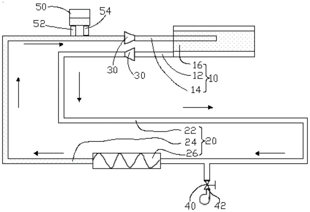
[0032] see figure 1 , the heat pipe cooling system includes a first pipeline 10, a second pipeline 20, and two pairs of quick connectors 30, the first pipeline 10 and the second pipeline 20 are open, and the two pairs of quick connectors 30 are connected to the first tube Between the pipeline 10 and the s...


PUM


Abstract

The present invention discloses a heat pipe cooling system, which comprises a first pipeline (10) and a second pipeline (20). The first pipeline (10) comprises a first steam pipe (12), a first liquid pipe (14) and an evaporation section (16) connected between the first steam pipe (12) and the first liquid pipe (14). The second pipeline (20) comprises a second steam pipe (22), a second liquid pipe (24) and a heat exchanger (26) connected between the second steam pipe (22) and the second liquid pipe (24). Two pairs of quick connectors (30) are respectively connected between the first steam pipe (12) and the second steam pipe (22), and between the first liquid pipe (14) and the second liquid pipe (24). In this way, the first pipeline (10) and the second pipeline (20) are combined to form a loop heat pipe. The loop heat pipe comprises a valve (40) for vacuum pumping and an interface (42). A refrigerant is arranged inside the loop heat pipe. The evaporation section (16) is internally provided with a capillary structure so as to provide a capillary pumping force for driving the refrigerant to circulate in the loop heat pipe. The heat pipe cooling system of the present invention is high in heat transfer efficiency, good in reliability, and free of working medium leakage risk. The present invention also provides power equipment.

Description

technical field [0001] The invention relates to the technical field of heat dissipation, in particular to a heat pipe heat dissipation system and electric equipment. Background technique [0002] As the performance and density of IT devices become stronger and higher, the power consumption of the system increases. The traditional air cooling is gradually approaching the limit of its heat dissipation capacity due to the limitation of fan performance and system noise, while liquid cooling High capacity, low noise, more and more people's attention. [0003] In the prior art, the liquid cooling heat dissipation system applied in the cabinet is mainly composed of the cabinet, a circulation system and an external cold source. The circulation system brings the heat in the cabinet to the external cold source to realize heat dissipation. There are many single boards in the cabinet, and the single board is equipped with a heat dissipation pipeline to provide heat dissipation for the ...

Claims


Application Information

Patent Timeline
Patent Type & Authority Applications(China)
IPC IPC(8): H05K7/20F28D15/04
CPCF28D15/04H05K7/20672F28D15/0266H05K7/20327H05K7/20336H05K7/20681H05K7/20809H05K7/20381
Inventor 彭耀锋李志坚刘洪辉池善久
Owner XFUSION DIGITAL TECH CO LTD
Why Eureka
Try Eureka