Supercharge Your Innovation With Domain-Expert AI Agents!

Train running speed detection method and system based on ballastless track

A ballastless track and running speed technology, applied in railway signaling and safety, etc., can solve problems such as speed calculation error, speed measurement error, wheel diameter change, etc., and achieve the effects of easy control, reliable operation and simple maintenance.

Inactive Publication Date: 2017-03-08
ZHUZHOU CSR TIMES ELECTRIC CO LTD
View PDF6 Cites 6 Cited by
  • Summary
  • Abstract
  • Description
  • Claims
  • Application Information

AI Technical Summary

Problems solved by technology

However, there are some disadvantages in this method: 1) the axle shaft and the motor rotor are usually engaged by multi-stage gears, and the transmission ratio is distorted due to manufacturing tolerances and wear, which leads to errors in the calculation of vehicle speed; 2) the wheel is not a cylinder with equal radius, it is The taper of the train is flexible suspension between the wheel and the car body during operation, and the wheel will move left and right, causing the diameter of the wheel part in contact with the rail to always change, which will bring errors to the calculation of the speed; 3) the wheel is As a consumable part, the outer diameter of the tread of the wheel will gradually wear out as the train runs, resulting in a change in the wheel diameter, which will bring errors to the calculation of the vehicle speed; 4) When the traction force or braking force exceeds the maximum friction force when the train is running, the wheel will idling, At this time, although the wheel tread line speed is not the train running speed, it introduces a huge error to the speed calculation
[0004] To sum up, due to the speed sensor detection method currently used, the transmission ratio will be distorted due to manufacturing tolerances and wear, which will lead to errors in the calculation of the vehicle speed; the diameter of the part of the wheel that is in contact with the rail will change due to the serial movement of the wheel, giving the vehicle speed The calculation will bring errors; the wheel diameter will change due to the tread wear of the wheels, which will bring errors to the calculation of the vehicle speed; the wheel will idling and will introduce errors to the calculation of the vehicle speed
The GPS method also has the problem of signal loss in tunnels or mountainous areas, resulting in errors in vehicle speed measurement.

Method used


Image

  • Train running speed detection method and system based on ballastless track
  • Train running speed detection method and system based on ballastless track
  • Train running speed detection method and system based on ballastless track

Examples


Embodiment Construction

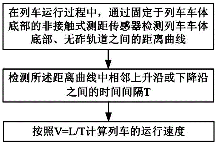
[0029] Such as figure 1 As shown, the steps of the train running speed detection method based on ballastless track in this embodiment include:

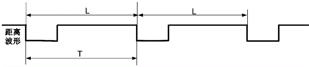
[0030] 1) During the operation of the train, the distance curve between the non-contact ranging sensor and the ballastless track is detected by the non-contact ranging sensor fixed on the bottom of the train body or the bogie. Arranged sleepers such as figure 2 As shown, the distance curve is a periodic square wave curve, and a periodic waveform in the distance curve is composed of the first distance of the sleeper area and the second distance of the non-sleeper area; see figure 2 , where L represents the distance between adjacent sleepers on the ballastless track, and T represents the time interval between adjacent rising or falling edges in the distance curve, that is, the time length of a periodic waveform (waveform period of the distance curve);

[0031] 2) The time interval T between adjacent rising or falling edges in the de...


PUM


Abstract

The invention discloses a train running speed detection method and system based on a ballastless track. The method comprises the following steps: detecting a distance curve between the bottom of a train body and the ballastless track through a non-contact distance measuring sensor in the train running process; detecting a time interval T between adjacent rising edges or falling edges in the distance curve; calculating the running speed of a train according to V=L / T, wherein V refers to the running speed of the train, and L refers to the distance between adjacent sleepers on the ballastless track; the system comprises a distance curve acquisition unit, a time interval detection unit and a speed calculation unit. The train running speed detection method and system based on the ballastless track have the advantages of high detection accuracy, no influences on measurement for wheel wear and idling, reliable operation and long service life of the non-contact measurement, no influences of weather or tunnels on the running speed calculation, capability of carrying out all-weather operation, no requirements on communication with the existing system of the train, easy expansion, simple structure, low cost and simple maintenance.

Description

technical field [0001] The invention relates to a running speed detection technology of a high-speed railway, in particular to a ballastless track-based train running speed detection method and system. Background technique [0002] With the continuous improvement of train speed, accurate real-time train speed is the basis for the normal operation of many on-board equipment. The accuracy of this data is directly related to the performance of train mileage marking positioning, traction, braking force control and other technologies. However, various train speed detection technologies currently used have certain disadvantages. At present, there are mainly two methods for calculating the running speed of trains, one is the speed sensor method, and the other is the GPS method. The speed sensor method is to install a speed sensor on the motor. By detecting the speed of the motor rotor and multiplying it by the transmission ratio between the axle and the motor, the speed of the whe...

Claims


Application Information

Patent Timeline
Patent Type & Authority Applications(China)
IPC IPC(8): B61L25/02
CPCB61L25/021
Inventor 贺文王俊平张敏张小珍张术毛慧华余虹宇沈云波兰强强王杰陈胜蓝
Owner ZHUZHOU CSR TIMES ELECTRIC CO LTD
Features
  • R&D
  • Intellectual Property
  • Life Sciences
  • Materials
  • Tech Scout
  • Unparalleled Data Quality
  • Higher Quality Content
  • 60% Fewer Hallucinations
Learn More