Composite type room temperature magnetic refrigeration system and direction control valve thereof

A directional control valve, compound technology, applied in refrigerators, refrigeration components, refrigeration and liquefaction, etc., can solve the problems of switching noise, cumbersome overall structure, loud noise, etc., to reduce additional power consumption, compact overall structure, improve The effect of efficiency

Active Publication Date: 2017-03-08
BAOTOU RES INST OF RARE EARTHS
View PDF5 Cites 34 Cited by
  • Summary
  • Abstract
  • Description
  • Claims
  • Application Information

AI Technical Summary

Problems solved by technology

[0009] However, in practical applications, the traditional composite room temperature magnetic refrigeration system uses multiple electromagnetic shut-off valves to control the switching of the flow direction of the heat transfer medium. The solenoid valves require additional power supply, and the solenoid valves are large in size and the switch is noisy.
Therefore, the traditional composite room temperature magnetic refrigeration system has the problems of high energy consumption, high noise, and cumbersome overall structure.

Method used


Image

  • Composite type room temperature magnetic refrigeration system and direction control valve thereof
  • Composite type room temperature magnetic refrigeration system and direction control valve thereof
  • Composite type room temperature magnetic refrigeration system and direction control valve thereof

Examples


Embodiment Construction

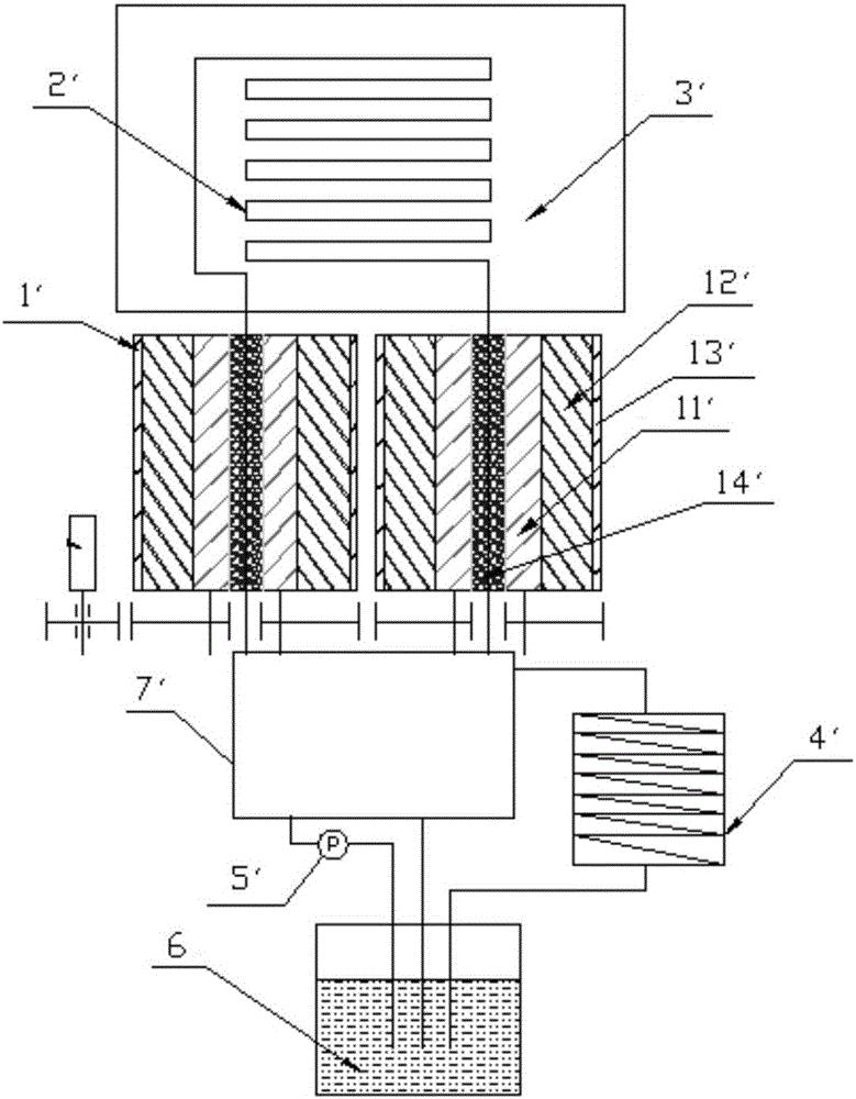
[0048] The invention provides a directional control valve with simple and compact structure, low energy consumption and low noise to replace multiple solenoid valves used in the current composite room temperature magnetic refrigeration system. On this basis, the present invention also provides a composite room temperature magnetic refrigeration system including the directional control valve.

[0049] In order to facilitate a better understanding of the technical solution of the present invention, the specific structure of the composite room temperature magnetic refrigeration system and its directional control valve will now be described in detail with reference to the accompanying drawings.

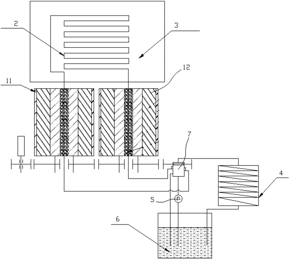
[0050] See image 3 and Figure 4 ,in, image 3 A schematic structural view of the compound room temperature magnetic refrigeration system provided by the present invention is shown, Figure 4 A schematic structural view of a specific embodiment of the directional control valve provide...


PUM


Abstract

The invention discloses a composite type room temperature magnetic refrigeration system and a direction control valve thereof. The direction control valve comprises a valve body and a valve element which rotate relatively; the valve body is provided with a valve body pump hole, a valve body hot end hole, a valve body liquid storage box hole, a valve body clockwise rotation magnetic hole and a valve body reversion magnetic hole, wherein the valve body pump hole and the valve body hot end hole oppositely extend in the direction of the rotating axis, and the valve body liquid storage box hole, the valve body clockwise rotation magnetic hole and the valve body reversion magnetic hole are formed in a staggered manner in the circumferential direction; the valve element is provided with a valve element pump flow channel and a valve element hot end flow channel which are arranged in a staggered manner in the circumferential direction; when the refrigeration system is in a first heat exchange mode; the valve body pump hole is communicated with the valve body clockwise rotation magnetic hole through the valve element pump flow channel, and the valve body hot end hole is communicated with the valve body reversion magnetic hole through the valve element hot end flow channel; when the refrigeration system is in a second heat exchange mode, the valve body pump hole is communicated with the valve body reversion magnetic hole, and the valve body hot end hole is communicated with the valve body clockwise rotation magnetic hole; and when the refrigeration system is in a first and second non-heat-exchange mode, the valve body pump hole is communicated with the valve body liquid storage box hole. The direction control valve effectively reduces the extra power consumption on the basis of meeting various technical performance indexesof a refrigerating machine, improves the efficiency of the refrigerating machine, and makes the overall structure compact and noise low.

Description

technical field [0001] The invention relates to the technical field of heat exchange medium flow direction switching control in a composite room temperature magnetic refrigeration system, in particular to a composite room temperature magnetic refrigeration system and a direction control valve thereof. Background technique [0002] Refrigeration technology is widely used in people's daily life, industry, agriculture and other fields. The refrigeration industry consumes a lot of energy. The gas compression refrigeration technology currently used has some disadvantages such as high energy consumption, low efficiency, and the exhaust gas destroys the ozone layer of the atmosphere and causes the greenhouse effect. The refrigeration industry is a big energy consumer and polluter, and it is one of the projects that require energy conservation and emission reduction. Therefore, research and development of a new type of refrigeration technology with low energy consumption and no pol...

Claims


Application Information

Patent Timeline
Patent Type & Authority Applications(China)
IPC IPC(8): F16K11/083F25B21/00F25B41/04F25B41/20
CPCF16K11/0836F25B21/00F25B41/20Y02B30/00
Inventor 李晨辰黄焦宏金培育王强张成刘翠兰张英德程娟李兆杰
Owner BAOTOU RES INST OF RARE EARTHS
Why Eureka
Try Eureka